EasyManuals Logo

Carel pCO Series User Manual

Carel pCO Series
84 pages
To Next Page IconTo Next Page
To Previous Page IconTo Previous Page
Page #60 background imageLoading...
Page #60 background image
pCO Sistema
Code: +030220336 - rel. 1.5 - 22/12/10
60
pCO
pCOpCO
pCO
XS
XSXS
XS
230/24 Vac
M
OUT
+V
analog output 1 (0/10 Vdc)
analog output 2 (0/10 Vdc)
analog output 3 (PWM taglio di fase/ phase cutting)
L
N
digital input 1
digital input 2
digital input 3
digital input 4
digital input 5
digital input 6
digital output 1
digital output 2
digital output 3
digital output 4
digital output 5
probe 3 (0/5 V )
p
robe 4 (Carel NTC)
probe 2 (4/20 mA)
probe 1
(0/1 Vdc o 4/20 m A )
G
G0
SYNC
B1
B2
B3
B4
GND
+5VREF
+24VDC
Y1
Y2
Y3
GND
ID1
ID2
ID3
ID4
ID5
ID6
IDC1
RXTX-
RXTX+
GND
TLAN
GND
C1
NO1
NO2
NO3
C4
NO4
NO5
C5
NC5
J1
J5
J6
J7
J8
J9
J10
J11
J2
J3
J4
CLOCK CARD
SERIAL CARD
built-in terminal
xs
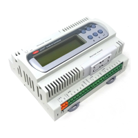
Fig. 8.c
Fig. 8.cFig. 8.c
Fig. 8.c

Table of Contents

Other manuals for Carel pCO Series

Questions and Answers:

Question and Answer IconNeed help?

Do you have a question about the Carel pCO Series and is the answer not in the manual?

Carel pCO Series Specifications

General IconGeneral
ConnectivityRS-485, Ethernet
DisplayLCD
Input/OutputConfigurable
Power Supply24 VAC/DC
TypeProgrammable Controller
Analog OutputsUp to 4
Serial CommunicationRS-485
ProtocolsModbus
Input Voltage24 VAC/DC
Protection RatingIP20
CommunicationRS-485, Ethernet
Relay OutputsUp to 8

Related product manuals