2
1 - INSTALLATION GUIDE
1.1. DESCRIPTION OF THE CONTROLLER AND COMPONENTS
- CONTROL BOARD
The main board is the core of the controller.
It is made of:
# a section which includes the microprocessor and the memory for the machine
control algorithm;
# an I/O section which allows interfacing with controlled devices by means of a plug-
in terminal.
# a section devised for interfacing with supervisory network and terminal which can
be installed in a remote position.
The control board represents the core of the system as it contains the
microprocessor which performs the control algorithm and the user interface
management. This board is connected to a pCO terminal and to any options.
NO11
C11
NC11
VG1
Y1
B1
AVSS
B2
B3
B4
B5
B6
AVSS
AVSS
J14
J15
G
G0
ID11R
ID11 (24V)
ID12R
ID12 (24V)
NO10
C10
NC10
NO9
C9
NC9
NO8
C8
NO7
C7
NO6
C6
NO13
C13
RS422
B8
B7
+24
IDCM2
ID10
ID9
ID8
ID7
ID6
IDCM1
ID5
ID4
ID3
ID2
ID1
NO12
C12
NO5
C5
NO4
C4
NO3
C3
NO2
C2
NO1
C1
R1
R2
R3
R4
R5
R6
R7
R8
R9
R10
R11
R12
R13
1
2
3
4
5
6
VG0
Y0
IC3
ID11 (220V)
ID12 (220V)
J28
J29
7
8
J17
J1
J19
J20
J21
J2
J3
J22
J4
J5
J24
J6
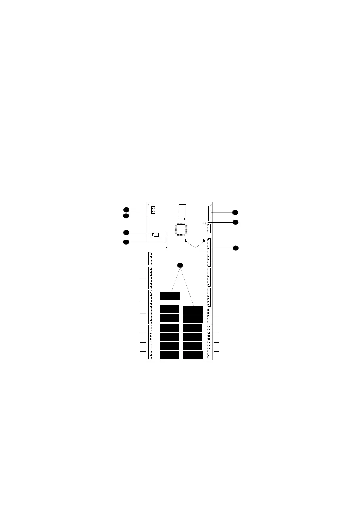
- List of components:
(1) 24 Vac supply cable
(2) Telephone cable connector for terminal connection (RS485) or for local
network connection
(3) Optional Clock board
(4) Optoisolated RS422 board for serial line connection for supervision and
telemaintenance
(5) Pin strip to select B5 and B6 voltage or current inputs
(6) Eprom with the programme
(7) Pin strip to select B28 and B29 voltage or current inputs
(8) Relay outputs
Rxx: Connectors for digital relay outputs

 Loading...


