3
No: Normally open contact
Nc: Normally close contact
C : Common reference for contacts
ID : Digital inputs
IDCM: Common reference for digital inputs
Bx : Analogue input
AVSS: Reference for analogue outputs
Yx: Analogue outputs
VG1/0: 24V A.C. Analogue outputs power supply
- USER INTERFACE
Here below are listed all components of pCO control kit.
The terminal allows exchange of information by means of a LCD which displays the
values of all controlled parameters, selected set-points, alarm thresholds and in
general all data concerning the controlled variables in the specified formats.
Moreover, the display will show particular messages any time an alarm condition
occurs. A keypad allows the setting of configuration parameters such as set-points,
alarm thresholds, alarm activation delays, etc. ...
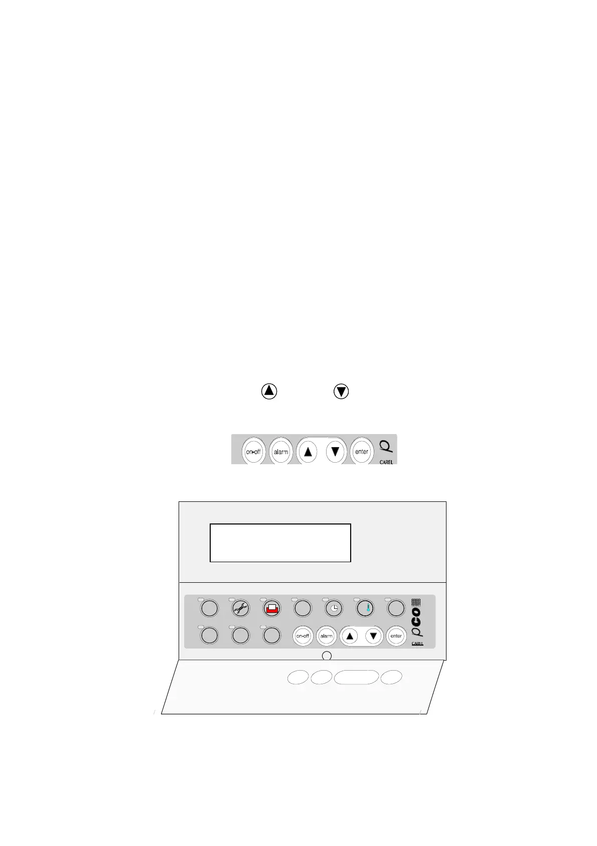
The visible rubber buttons, which can be seen and pressed even when the front door
is closed, are the most important and the most used ones, above all when the
machine is ON.
The above quoted buttons are the following:
-1-
ON/OFF button;
-2-
Buzzer silencing
and
alarm deactivating
button;
-3-
button;
-4-
button;
-5-
ENTER button.
- FRONT PANEL
menu'
I/O set
prog.
estate
inver.
?
info
This is the control board front panel. The 4X20 LCD on the panel displays the values
measured by the probes, working parameters and all necessary information for a
12
34
5

 Loading...


