S&2ð
cod. Carel +030221826 rel. 2.0 dated 03/10/02
16
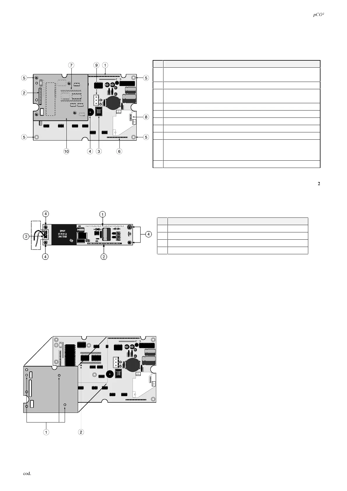
*UDSKLFGLVSOD\ERDUG
The board supports the microprocessor, the memory and the EPROM which holds the application program for managing the display
and the keypad. It also includes a connector for the optional serial card for printer management (code PCOSERPRN0) and for the
card containing the clock and the 32 of EEPROM. Here below are described the components of the terminal with graphic display.
Q GHVFULSWLRQ
1 connector to the inverter and signal management card for the
display
2 connector for the optional printer card
3 telephone-type connector card for terminal connection to the
pCO
2
(PCOB*21) or junction TCONN6J000
4 buzzer for acoustic alarm signals
5 metal-plated mounting holes
6 connector for connection to an additional keypad card
7 EPROM program and mounting/direction orientation
8 connector for real time clock/32kB EEPROM
9 power connector (to be used with PCOI00PGL0 and for distances
over 50 metres with PCOT00PGH0) - cross sections: from min 0,5mm²
to max. 2,5mm²).
10 protective screen
7DE
,QYHUWHUFDUGIRUSRZHULQJWKHIOXRUHVFHQWOLJKWRQWKHGLVSOD\&)/DQGFRQQHFWLQJWRWKHS&2
This card provides power to the fluorescent back-lighting on the display and allows the main board to correctly control the
display used. The fluorescent light is available only on PCOI00PGLO, 240x128 pixels.
Q GHVFULSWLRQ
1 connection to the pCO display for model PCOI00PGL0
2 connection to the display (LCD)
3 connection to the light
4 mounting holes
7DE
:$51,1*: The dotted area in Fig. 3.9.2.1 indicates the high voltage area (around 360 Vac); do not in any circumstances touch
this area with your fingers or with conducting tools.
3URWHFWLYHVFUHHQRSWLRQDOSULQWHUFDUG
For all pCO graphic terminal models an optional card can be inserted in the pin connector marked by number 2 as shown in Fig.
3.9.3.1. for managing a serial printer. To insert the card, first remove the protective screen which is found in the area reserved for
the optional printer card. The function of the screen is to increase immunity against terminal disturbances. Mounting is made by
tightening the three screws in the three holes marked by no.1, Fig. 3.3.1.3.1.
)LJ
)LJ
)LJ
 Loading...


