S&2ð
cod. Carel +030221826 rel. 2.0 dated 03/10/02
23
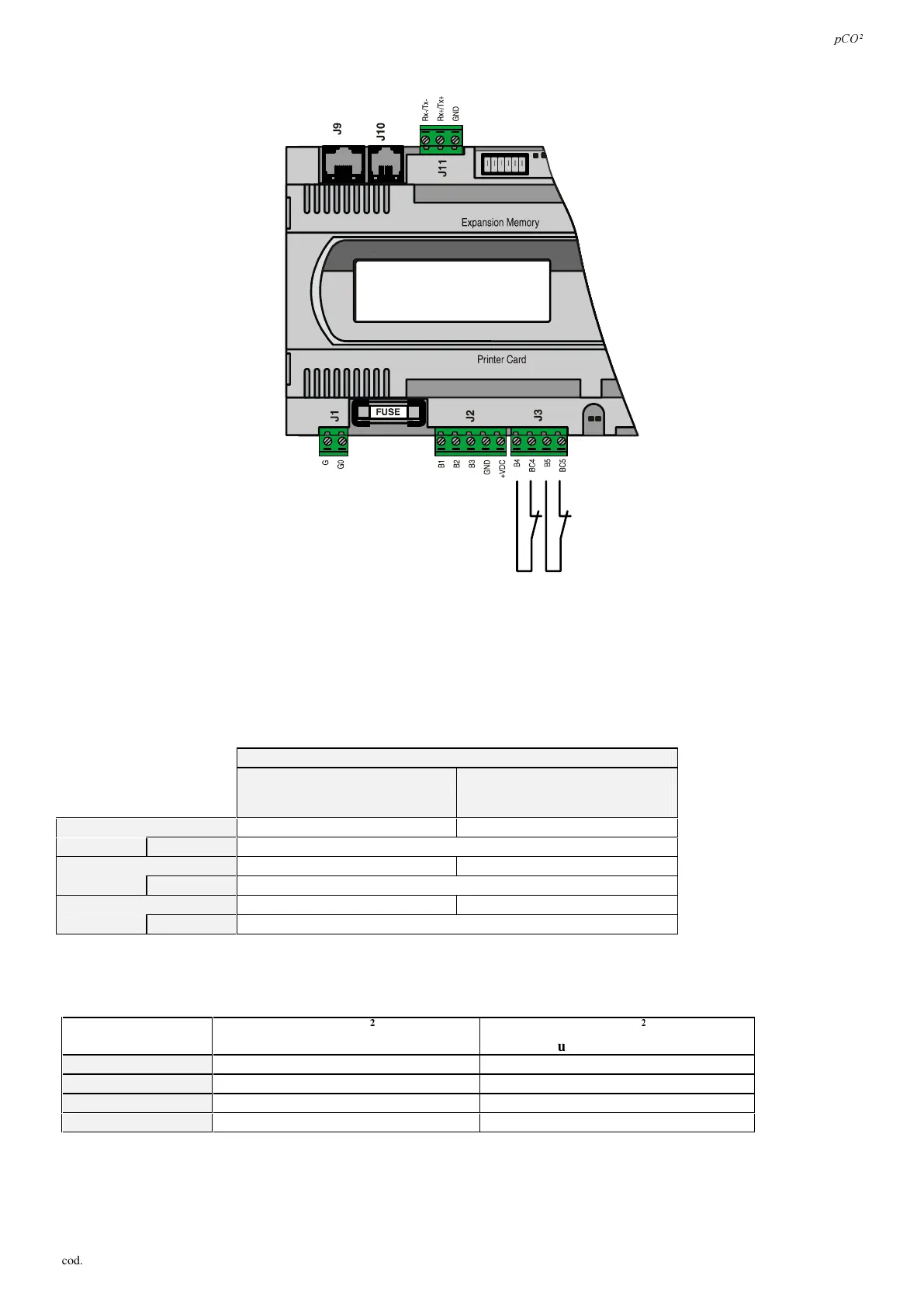
&RQQHF WLQJ W KH2 12 ) ) VH OHF WD EOHD QD ORJ XHLQSXW V
)LJ
The pCO
2
allows some analogue inputs to be configured as clean digital inputs. The inputs in question are B4, B5, B9, B10. The
inputs must be pre-configured as clean digital inputs by the application software resident in the flash memory. The following
shows the connection diagram:
:$51,1*6: The maximum current delivered by the digital input is 5mA (thus the rating of the external contact must be at
least 5mA). These inputs are not optically-isolated.
7DEOHVXPPDU LVLQJ W KH D QD OR JXH LQSXW VDFFRUGLQJWRWKHDYDLODEOHYHUVLRQV
DQDORJXHLQSXWV
SDVVLYH
17&37DQG212))
XQLYHUVDO
·9·9
·P$·P$DQG17&
60$//
2 (B4, B5) 3 (B1, B2, B3)
WRWDO
5
0(',80
2 (B4, B5) 6 (B1, B2, B3, B6, B7, B8)
WRWDO
8
/$5*(
4 (B4, B5, B9, B10) 6 (B
1
, B
2
, B
3
, B
6
, B
7
, B
8
)
WRWDO
10
7DE
When remoting the analogue inputs, the cross section of the leads must be as reported in the following table (Tab. 4.4.6.2)
LQSXWW\SH VL]HPP
IRUXSWRPORQJOHDGV
VL]HPP
IRUXSWRPORQJOHDGV
17&
0,5 1,0
37
0,75 1,5
,FXUUHQW
0,25 0,5
9YROWDJH
0,25 0,5
7DE
 Loading...


