S&2ð
cod. Carel +030221826 rel. 2.0 dated 03/10/02
30
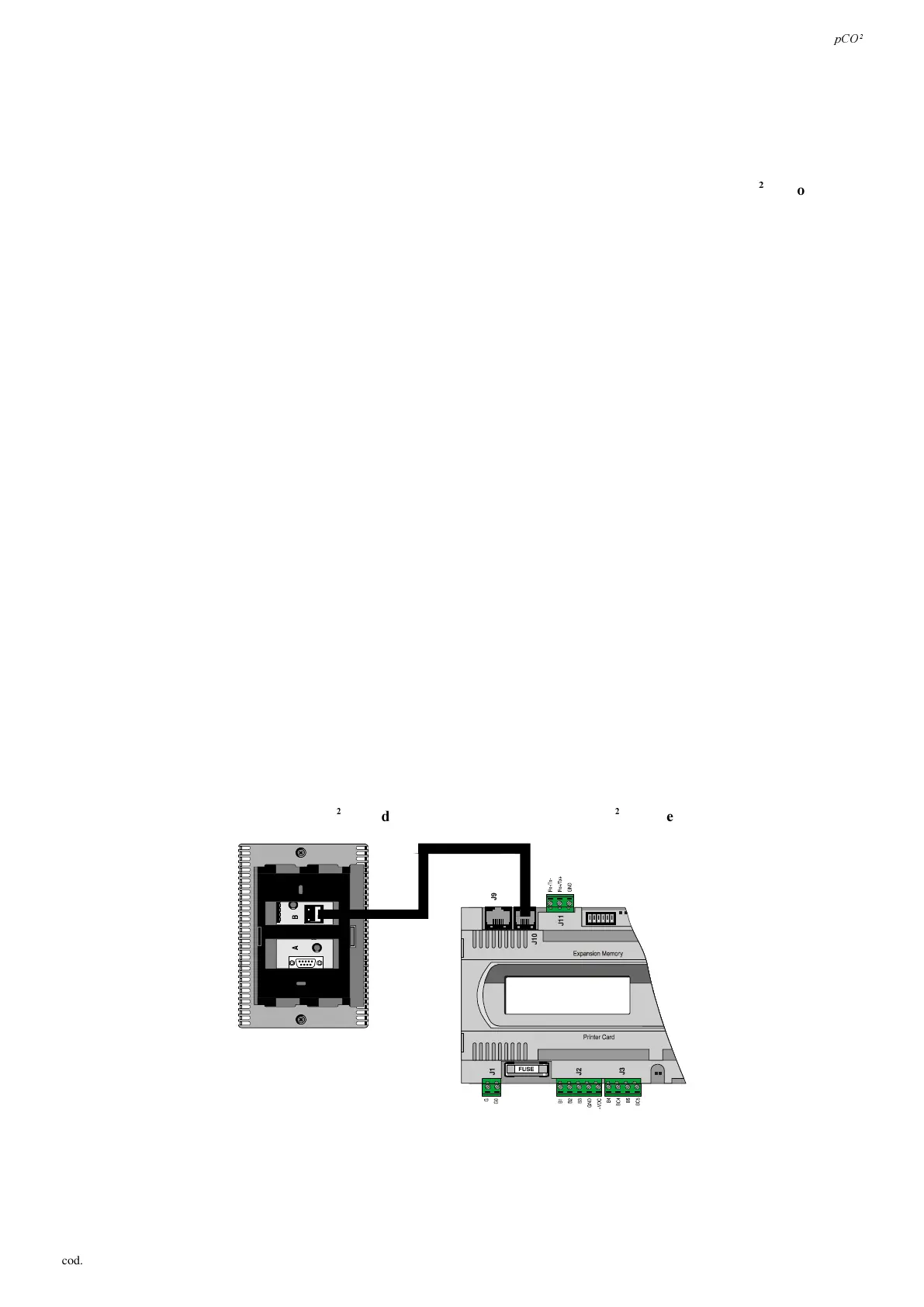
,QVWDOOLQJWKHXVHUWHUPLQDO
The connection between the user terminal and pCO
2
is made using a 6-way telephone cable supplied by Carel.
To make the connection simply insert the telephone connector in terminal J10 of the pCO
2
and in terminal B on the user
terminal. Insert the connector fully into in the terminal until it clicks into place.
To remove the connector simply press lightly on the plastic flap and remove the cable.
The pCO
2
can also work without the terminal; GRQRWGLVFRQQHFWDQGWKHQUHFRQQHFWWKHWHUPLQDOWRWKHS&2
ZLWKRXWILUVW
KDYLQJZDLWHGDURXQGVHFRQGV (if the operation is performed with the machine on).
When standard terminals – connected by J10 - of domestic or similar use devices, thus subjected to CEI EN 55014-1 - 04/98
direction, DUHUHPRWHG, they must have shielded cable. The shield must be connected to the GND terminal of J11.
Inserire figura appropriata.
,QVWDOOLQJ W KHZ D OOSDQH O PRXQWLQJ W H UPLQDOV S&2 7 DQGU H ODW LY HH OH F WU LF DOF R QQHF W LRQV
This type of terminal has been designed for panel mounting and wall-mounting. The drilling template, in the case of panel
mounting, must measure 167x108 mm.
When installing pay attention to the following instructions;
1. unscrew the two screws on the rear cover of the terminal, and remove the cover;
2. rest the front cover against the front part of the panel;
3. insert the cover from the rear, lining up the two holes with the two studs positioned on the front cover;
4. tighten the screws.
The maximum thickness of the panel is 6 mm. Then perform the electrical connections. The wall-mounting features the use of the
special mounting brackets and standard 3-module wall-mounting switch box to allow the passage of the cables. Fasten the bracket to
the wall, using the screws; finally, make the electrical connections and click the rear the of instrument onto the bracket.
The electrical connections are the following. Connect the telephone cable (code S90CONN00*) from the power board (code PCOB*
and PCO2*) into the relative jack. The model with graphic display (code PCOT00OGH0) is fitted with a further screw terminal block.
,QVWDOOLQJ W KH SD QHO PRXQW H GW HU PLQDOV S& 2, D QGU HOD W LY H H OHF W U LF DOF R QQH F WLR QV
These terminals have been designed for panel mounting; the drilling template must measure 173x154 mm. When installing refer
to the following instructions;
1. remove the click-on frame;
2. insert the plastic part containing the display and electronic boards on the drilled front part of the panel making sure the gasket
on the lower edge of the front cover rests properly against the front part of the panel;
3. make four 2.5mm diameter holes in the panel, in line with the holes in the instrument;
4. insert the fastening screws supplied, choosing between self-tapping and self-threading screws according to the type of
material used for the panel (plastic or metal).
Then perform the electrical connections.
The electrical connections are the following. Connect the telephone cable (code S90CONN00*) from the power board (code PCO2*)
into the relative jack. For the model PCOI00PGL0 only connect the 24Vac (30VA) power supply to the screw terminal block. ,I
WKHVDPHWUDQVIRUPHULVXVHGIRUWKHS&2
*DQG*PXVWEHWKHVDPHIRUWKHS&2
DQGWKHWHUPLQDO.
)LJ
 Loading...


