S&2ð
cod. Carel +030221826 rel. 2.0 dated 03/10/02
36
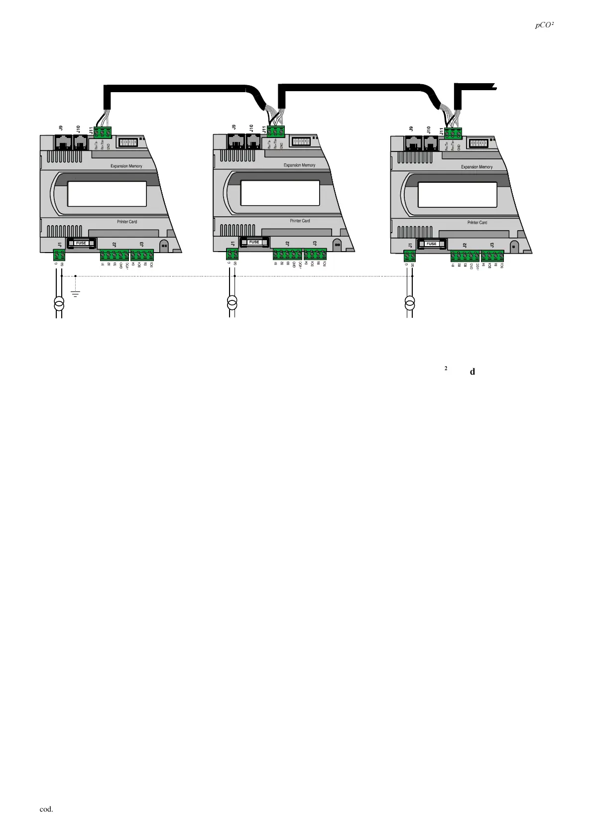
Fig. 5.4.2 shows a diagram of a number of boards connected in a pLAN network and powered by different transformers with the
same earth reference. Typical application: a number of boards inside different electrical panels.
AWG 20/22
AWG 20/22
AWG 20/22
)LJ
,03257$17:$51,1*6
• WKHJURXQGFRQQHFWLRQPXVWEHPDGHWRWKHVDPHJURXQGVDPHJURXQGSROHIRUDOOWKHS&2
ERDUGV
• ZLWKWKHVHFRQILJXUDWLRQV)LJV&ODVV,,VDIHW\WUDQVIRUPHUVPXVWEHLQVWDOOHG
5HPRWHL QVWDOODWL RQRIWKHWHUPLQ DOLQDS/$1QHWZRUN
When pCO
2
boards are connected in a pLAN network the terminal can be remotely-located ad a distance of up to 50 metres if
using a telephone-type cable; if using a shielded cable, it can be located at a distance of up to 200 metres. The following figures
show the connection diagrams for the various configurations.
 Loading...


