4.6 Collegamento delle uscite analogiche
Il pCO
2
fornisce fino a sei uscite analogiche a 0/10 V optoisolate
alimentate esternamente a 24 Vac/Vdc. La Fig. 4.6.1 rappresenta lo
schema elettrico di collegamento; la tensione 0 V (zero)
dell'alimentazione è anche il riferimento di tensione delle uscite.
La Tab. 4.6.1 riassume la distribuzione delle uscite analogiche in
funzione delle versioni disponibili.
n. uscite analogiche
SMALL 4
MEDIUM 4
LARGE 6
Tab. 4.6.1
Le sezioni dei cavi relativamente alla remotazione delle uscite digitali,
sono riportate nella tabella 4.5.4.2
4.7 Collegamento delle uscite digitali
Il pCO
2
prevede fino a 18 uscite digitali con relè elettromeccanici.
Per facilità d'assemblaggio i morsetti comuni di alcuni relè sono stati
raggruppati. Nel caso in cui si utilizzi lo schema di Fig. 4.7.1, la corrente
che interessa i morsetti comuni non deve superare la portata (corrente
nominale) di un singolo morsetto.I relè sono divisi in gruppi, a
seconda della distanza di isolamento. All’interno di un gruppo, i relè
hanno tra loro isolamento singolo e quindi devono essere sottoposti alla
stessa tensione (generalmente 24 Vac o 110/230 Vac).Tra i gruppi c’è il
doppio isolamento quindi i gruppi possono essere a tensione diversa.
4.7.1 Uscite digitali a relè elettromeccanici
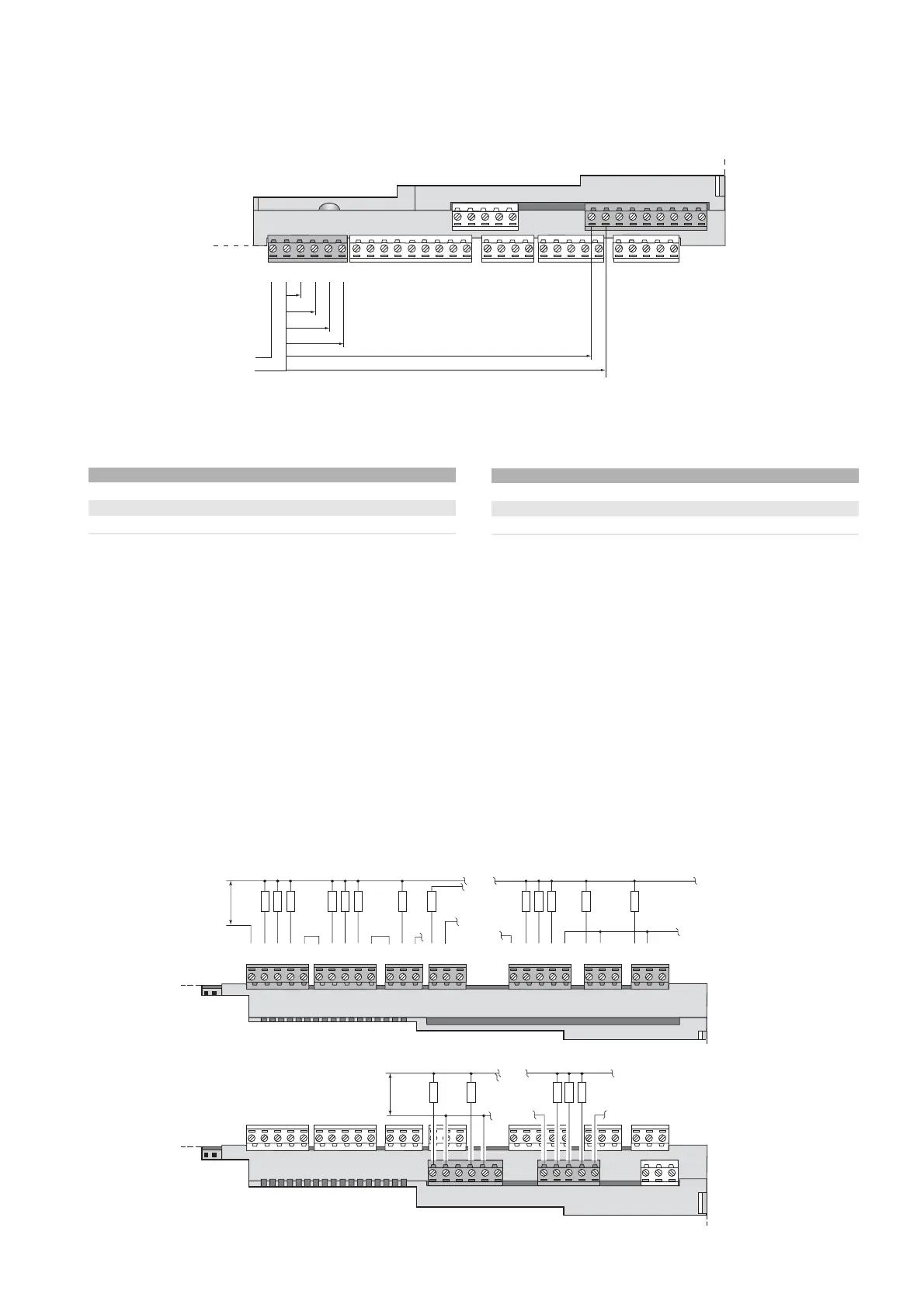
4.6 Connecting the analogue outputs
The pCO
2
provides up to six optically-isolated 0/10V analogue outputs
powered externally at 24Vac/Vdc. Fig. 4.6.1 shows the connection
wiring diagram; the 0V (zero) voltage of the power supply is also the
reference for the voltage of the outputs.
Ta b. 4.6.1 summarises the distribution of the analogue outputs accor-
ding to the available versions.
no. analogue outputs
SMALL 4
MEDIUM 4
LARGE 6
Tab. 4.6.1
When remoting the analogue inputs, the cross section of the leads
must be as reported in the following table (Tab. 4.5.4.2)
4.7 Connecting the digital outputs
The pCO
2
features up to 18 digital outputs with electromechanical
relays; upon request with solid state relays (SSR).
To simplify assembly the common terminals of some relays have been
grouped together. If the diagram in Fig. 4.7.1 is used, the current at
the common terminals must not exceed the rating (nominal cur-
rent) of a single terminal, that is 8A resistive.The relays are divided
into groups, according to the distance of insulation.Inside each group,
the relays have just single insulation and thus must have the same
voltage (generally 24Vac or 110/230Vac). Between the groups there is
double insulation and thus the groups can have different voltages.
4.7.1 Electromechanical relay digital outputs
31
pCO
2
- cod. +030221835 rel. 3.0 - 18.02.03
 Loading...


