19
+050003290 - 1.4 - 29.09.2006
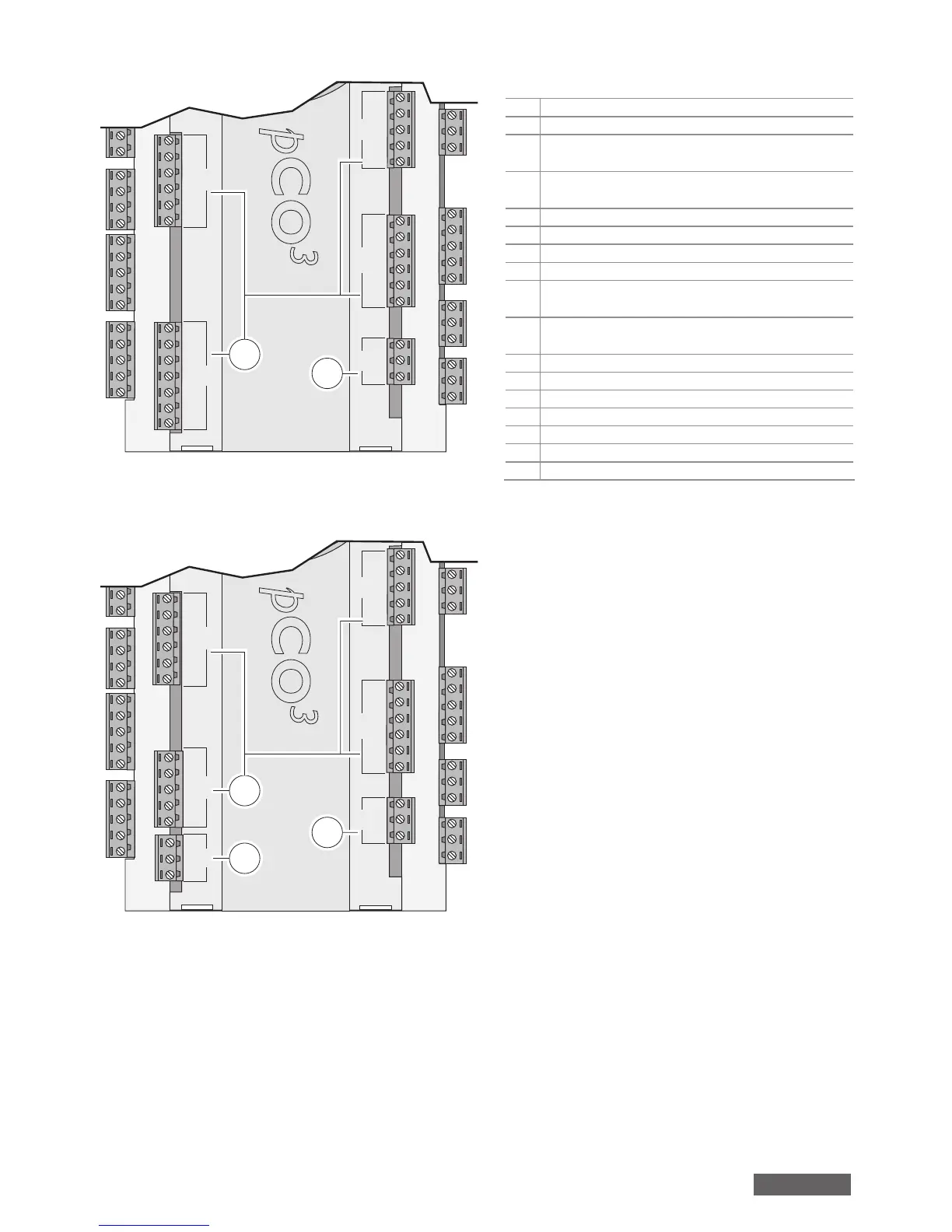
EXTRALARGE N.O. version
J20
J21 J22 J23
J19
C14
NO14
NO15
NO16
C14
C17
NO17
NO18
NO19
NO20
C17
E-
E+
GND
C25
NO25
NO26
NO27
NO28
NO29
C25
C21
NO21
NO22
NO23
NO24
C21
12
11
Fig. 4
EXTRALARGE N.C. version
J20 J25
J21 J22 J23
J19
C14
NC14
NC15
NC16
C14
C17
NC17
NC18
NC19
NC20
C17
E-
E+
GND
B9
B10
BC9
C25
NC25
NC26
NC27
C25
C21
NC21
NC22
NC23
NC24
C21
5
12
11
Fig. 5
Key (Figs. 3 to 5)
1.
power supply connector [G (+), G0 (-)];
2.
yellow power LED and 3 LEDs for the pLAN networks;
3.
additional power supply (max. 200 mA) for the
terminal and 0 to 5 V ratiometric probes;
4.
universal NTC, 0 to 1 V, 0 to 5 V ratiometric, 0 to 10 V,
0 to 20 mA, 4 to 20 mA analogue inputs;
5.
passive NTC, PT1000, ON/OFF analogue inputs;
6.
0 to 10 V analogue outputs;
7.
24 Vac/Vdc digital inputs;
8.
230 Vac or 24 Vac/Vdc digital inputs;
9.
connector for terminal display (external panel with
direct signals);
10.
connector for all the standard pCO series terminals
and for downloading the application software;
11.
digital relay outputs;
12.
connector for the I/O board expansion;
13.
pLAN connector;
14.
cover for inserting the optional supervisor serial board;
15.
cover for inserting the optional fi eld board;
16.
cover for inserting the optional service board;
17.
Built-In terminal (LCD, buttons and LEDs).
english
 Loading...


