29
+050003290 - 1.4 - 29.09.2006
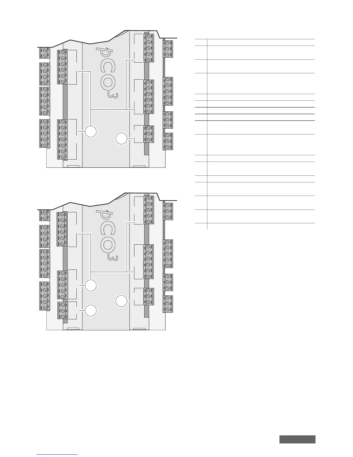
Version EXTRALARGE N.O.
J20
J21 J22 J23
J19
C14
NO14
NO15
NO16
C14
C17
NO17
NO18
NO19
NO20
C17
E-
E+
GND
C25
NO25
NO26
NO27
NO28
NO29
C25
C21
NO21
NO22
NO23
NO24
C21
12
11
Abb. 4
Version EXTRALARGE N.C.
J20 J25
J21 J22 J23
J19
C14
NC14
NC15
NC16
C14
C17
NC17
NC18
NC19
NC20
C17
E-
E+
GND
B9
B10
BC9
C25
NC25
NC26
NC27
C25
C21
NC21
NC22
NC23
NC24
C21
5
12
11
Abb. 5
Legende (Abb. 3…5)
1.
Versorgungsstecker [G (+), G0 (-)];
2.
gelbe Versorgungs-LED und 3 LEDs für das lokale
pLAN-Netzwerk;
3.
zusätzliche Versorgung für Bedienteil und
ratiometrische 0…5 V-Fühler;
4.
universale analoge NTC-, 0…1 V-, 0…5 V,
ratiometrische 0…10 V-, 0…20 mA-, 4…20 mA-
Eingänge;
5.
passive analoge NTC-, PT1000-, EIN/AUS-Eingänge;
6.
analoge 0…10 V-Ausgänge;
7.
digitale 24 Vac/Vdc-Eingänge;
8.
digitale 230 Vac- oder 24 Vac/Vdc-Eingänge;
9.
Steckverbinder für das synoptische Display
(externe Tafel mit direkten Anzeigen);
10.
Steckverbinder für alle Standard-Bedienteile
der pCO-Serie und für das Download des
Anwendungsprogramms;
11.
digitale Relaisausgänge;
12.
Steckverbindung für den Anschluss an die E/A-
Erweiterungsplatine;
13.
Steckverbinder für pLAN;
14.
Klappe für das Einstecken der optionalen seriellen
Überwachungsgerät-Karte;
15.
Klappe für das Einstecken der optionalen Field-
Karte;
16.
Klappe für das Einstecken der optionalen Service-
Karte;
17.
Built-in-Bedienteil (LCD, Tasten und LEDs).
deutsch
 Loading...


