20
+0500040RU - 1.2 - 07.06.2011
ENG
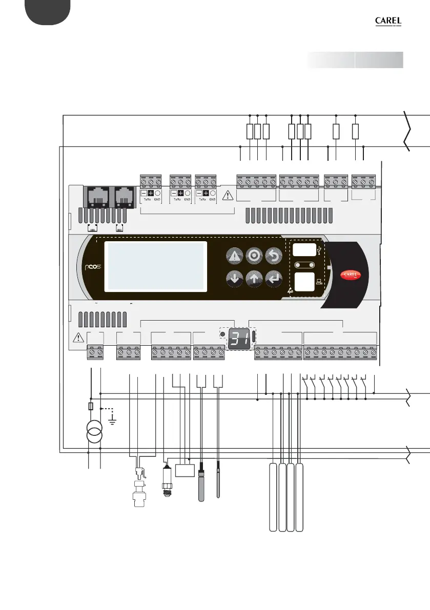
EXAMPLE: GENERAL WIRING DIAGRAM
230/24 Vac
M
OUT
+V
analog output 1 (0/10 Vdc)
analog output 2 (0/10 Vdc)
analog output 3 (0/10 Vdc)
analog output 4 (0/10 Vdc)
L
N
digital output 1
digital output 2
digital output 3
digital output 4
digital input 1
digital input 2
digital input 3
digital input 4
digital input 5
digital input 6
digital input 7
digital input 8
digital output 5
digital output 6
digital output 7
digital output 8
probe 1 (0/5 V)
probe 2 (4/20 mA)
probe 3
(0/1 Vdc or 4/20 mA)
probe 4 Carel NTC
probe 5 PT1000
Rx-/Tx-
Rx+/Tx+
GND
C1
NO1
NO2
NO3
C1
C4
NO4
NO5
NO6
C4
C7
NO7
C7
NO8
C8
NC8
G
G0
B1
B2
B3
GND
+VDC
+Vterm
GND
+5 VREF
B4
BC4
B5
BC5
VG
VG0
Y1
Y2
Y3
Y4
ID1
ID2
ID3
ID4
ID5
ID6
ID7
ID8
IDC1
SMALL
C1
NO1
NO2
NO3
C1
C4
NO4
NO5
NO6
C4
C7
NO7
C7
NO8
C8
NC8
G
G0
B1
B2
B3
GND
+VDC
+Vterm
GND
+5 VREF
B4
BC4
B5
BC5
VG
VG0
Y1
Y2
Y3
Y4
ID1
ID2
ID3
ID4
ID5
ID6
ID7
ID8
IDC1
B6
B7
B8
GND
J1 J24 J2 J3
J4 J5
J14
J11 pLAN
J10J9
J13J12
J16
J15
J6
FieldBus card BMS card
J25 BMS2
J26 FBus2
input: 24 V 50...60 Hz / 28...36 V
max. power: 45 VA/20 W
Rx-/Tx-
Rx+/Tx+
GND
Rx-/Tx-
Rx+/Tx+
GND
50VA
2.5 AT
Fig. 8
 Loading...


