CAREL Industries HQs
Via dell’Industria, 11 - 35020 Brugine - Padova (Italy)
Tel. (+39) 0499716611 – Fax (+39) 0499716600 – www.carel.com – e-mail: carel@carel.com
+05C001950 - rel. 1.3 - 02.03.2020
CAREL⡄㒕⤜䊅㻩䐋ⱙ㾿ⶥ⥛㠘⭥㦉㑇᱄
CAREL INDUSTRIES reserves the right to modify the features of its products without prior notice.
Technical specifi cations
Display
Type LCD TFT
Resolution 800x480 Wide
Active display area 7” diagonal
Colours 16,7M
Backlighting LED - Lifetime 20 khrs @ 25 °C
Brightness control Yes - auto-o by default after 15 min
Visual angle (CR ≥10) Up/Down (50/70 deg.) - Left/Right (70/70 deg.)
Contrast (typical) 400 (Φ=0°)
Brightness (typical) 500 cd/m
2
User interface
Touchscreen Resistive
System signal LEDs 8-colour noti cation bar
Interfaces
ETH0, ETH1 Ethernet ports Auto-MDIX 10/100 Mbit - RJ45 female
STP CAT 5 cable Lmax = 100 m
Wi-Fi IEEE 802.11 b/g/n - STATION/ACCESS POINT mode
Built-in/external antenna based on model
Max Transmit Power = 17dBm
External antenna remote mounting Lmax = 2 m
External antenna connector RP-SMA female
(for models PG*07***D[G,I,R,W]***)
USB port () Host interface 2.0 - micro USB -B - 150 mA max
(do not use to charge devices) - Lmax = 1m
COM1 (), COM2 Serial ports RS485 max 115,2 Kb/s
Removable screw connector 3,81mm pitch
Shielded twisted pair cable AWG 20-22 for ±
Lmax = 500m - tightening torque 0.25Nm (2.2lbf x in)
Master/Slave set via dipswitch (Fig.3)
Temperature / humidity probe 0 to 50 °C / 20 to 80% rH
0 to 50 °C ±1 °C (static air)
20 to 80% ±5% (static air)
()
only for service. The USB port can be damaged by ESD (Electro-Static Discharges).
It’s recommended to adopt appropriate precautions in order to avoid failures.
() opto-isolated for model PGR07****[C,D,F,G,R]***
Functions
Vector graphics Yes, includes SVG 1.0 support
Dynamic objects Yes Visibility, position, rotation
TrueType fonts Yes
Multi-protocol Yes
Logs and trends Yes. Limited to Flash memory capacity
Multilanguage Yes, run-time language setting and limited only by
available memory
Recipes Yes. Limited to Flash memory capacity
Alarms Yes
Event list Yes
Passwords Yes
Real Time Clock () Yes, with backup battery
Screen saver Yes
Buzzer () “Beep” when pressing the touchscreen (settable)
() only on models where featured
Electrical
Power supply 24Vdc Class 2/SELV supplied by PGTA00TRX0 accessory
Lmax = 50 m (-)- cable cross section AWG 12-20
tightening torque 0.8 Nm (7 lbf x in)
Max Power Absorption 9 W
Fuse Automatic
Weight Approx. 600 g
Battery Non-rechargeable lithium model BR1225
Software class and structure A
Purpose of control operation control
Controller construction incorporated control (PG*07***[D,F,N,T,W]****)
Type of automatic action type 1 action
Heat and re resistance Cat. D
Overvoltage category Cat. III
Insulation class Class III
() For PG*07***W**** models with ush mounting, accessory PGTA00TRX0 must be
installed in a dedicated box - () Power supply range: 24 Vdc ± 10%
Environmental conditions
Operating temperature PG*07***[D,N,T]****: -20 to 60 °C
PG*07***[F,W]****: 0 to 50 °C
Storage temperature PG*07********: -30 to 70 °C
Maximum operating and
storage relative humidity
85% @ 40 °C non-condensing
Ingress protection PG*07***T****: IP66, NEMA Type 1 (front)
PG*07***N****: IP66, NEMA Type 4X indoor (front)
if coupled with PGTA**F [B,W][2,3]* (frame)
PG*07***[D,F,W]****: IP20, NEMA Type 1 (front)
Pollution degree 3
J1
J2
J3
J4 J5
J14
J10
J13
J12
J15
drac SMBdrac suBdleiF
4321
J11 pLAN
Tx/Rx
GND
J26 FBus2
J24
+
XXXXXXXXXXXX
ETH0 ETH0
c.pCO/pCO
Access-Point/Station
J1
J2
J3
J4 J5
J14
J10
J13
J12
J15
drac SMBdrac suBdleiF
4321
J11 pLAN
J25 BMS2
J26 FBus2
J24
+
XXXXXXXXXXXX
c.pCO
J1
J2
J3
J4 J5
J14
J10
J13
J12
J15
drac SMBdrac suBdleiF
4321
Tx/Rx
GND
J25 BMS2
J26 FBus2
J24
+
XXXXXXXXXXXX
c.pCO/pCO
GND
–
+
LN
+–
PGTA00TRX0
230 Vac
24 Vdc
+
–
GND
–
+
J25 BMS2
J11 pLAN
COM1
COM2
J1
J2
J3
J4 J5
J14
J10
J13
J12
J15
dracSMBdracsuBdleiF
4321
J11 pLAN
Tx/Rx
GND
J26 FBus2
J24
+
XXXXXXXXXXXX
c.pCO/pCO
Access-Point/Station
c.pCO mini
J1
J2
J3
J4
J5
J14
J10
J13
J12
J15
dracSMBdracsuBdleiF
4321
Tx/Rx
GND
J25 BMS2
Tx/Rx
GND
Tx/Rx
GND
J26 FBus2
J24
+
XXXXXXXXXXXX
c.pCO/pCO
GND
–
+
LN
+–
PGTA00TRX0
230 Vac
24 Vdc
+
–
GND
–
+
ETH1 ETH0
J25 BMS2
J11 pLAN
COM1
COM2
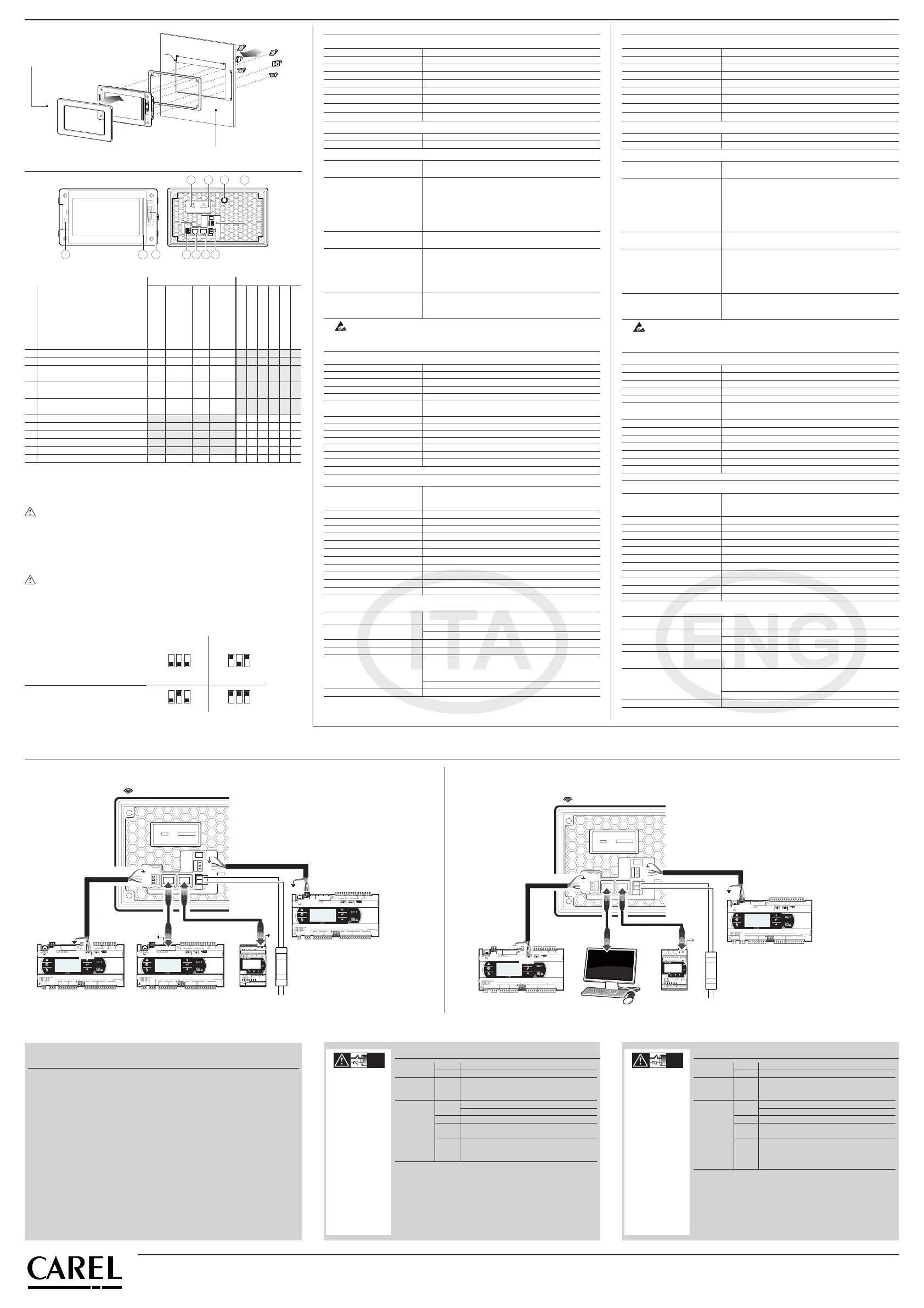
以太网开关配置 / Ethernet switch confi guration 双MAC以太网配置 / Dual MAC Ethernet confi guration
Fig. 4a
Fig. 4b
㶙㕈㑍ㅴ /
Network connection:
1 3 5
710 9 8 114
2
6
SW2
SW1
Fig.2
Mounting/➓䓑 Connectivity/㵉䁗
Description/㘉㭗
PG*07***[F,T]****
Front Panel/前面板
PG*07***N****
Front Panell /
前面板
PG*07***D****
Rear Panel /背板
PG*07***W****
Wall Mounting
墙面安装
PGR07****[B/W]***
PGR07****D***
PGR07****[C/R]***
PGR07****[F/G]***
PG*07****E***
PG*07****[I/M]***
1 MicroUSB rear/⡔㘇
2 MicroUSB front/䎞㘇
3
external keypad connector/
㶃䐤㾂ポ㝭㑍ㅴ㵘
4
temperature and humidity probe ()/㸣
Ⱙ⼮㬋Ⱙ⪌ⶱ㡘()
(option)
5
Wi-Fi antenna SMA connector (RP-SMA)
Wi-Fi 㳍㼀SMA㑍ㅴ㵘(RP-SMA)
6 RS485 port COM1/RS485Ⱜ㋻COM1
7 RS485 port COM2/RS485Ⱜ㋻COM2
8 Ethernet port ETH0/䄵㲌㶙㋻ETH0
9 Ethernet port ETH1/䄵㲌㶙㋻ETH1
10 noti cation bar/㵉䐋㎙
11 power supply/电源
Tab. 2
如果
COM1
端口用作
pLAN(Modbus㵉⺞pLAN㾎䅊)〓㻵㬟Ⱜ㋻㤌㹑䊻㶙㕈䐱⭥⭻䄜
⼮䔏⽔䄜㪉⡙㩰㑍ㅴ120㝘㚘⮈䔉᱄㋪㑍ㅴ⭞㶙㕈䐱⭥䔏⫔㪉⡙㭞㑠㸋32
䔏⧅㉁㏌㸋500m᱄
注意㆗
COM1
端口可用作
pLAN(Modbus㵉⺞pLAN㾎䅊)᱄
()Ⰹ㠻ネ⥊⪌ⶱ㡘㵉ⴈ㋸㬨㤆ㆁ⭥᱄
If COM1 port is used as pLAN (Modbus over pLAN) or display port: DO NOT connect the
resistors 120 ohm termination on the rst and last device in the network. The maximum
number of devices that can be connected in the network is 32 and the maximum length
of the network is 500m.
Attention: only COM1 port can be used as a pLAN (Modbus over pLAN protocol).
() Periodically check that the probe ventilation holes are clean.
串行DIP开关配置 / Serial
Dipswitch Con guration
SLAVE/从控 MASTER/主控
Fig.3
端口电阻
terminator resistor
120 ohm - OFF
123
ON
123
ON
123
ON
123
ON
Pull-Up
Pull-Down - OFF
Pull-Up
Pull-Down - ON
(pLAN)
端口电阻
terminator resistor
120 ohm - ON
㑍ㅴ⭞pCO/c.pCO㋹䐧㡘 /
Connection to
pCO/c.pCO
NEMA 4X前面板 / NEMA 4X Frontal
214
R2
116
Fig.1e
㶃㌓⥛㠘⫛㕌
PGTA**F[B,W][2,3]*
薄板厚度在 1.2~6 mm之间
Sheet thickness from 1.2 - 6 mm
ゝ㭖⺇ⷒ
㻵㬟㠢
㏁㾮
LCD TFT
⢇㔫
800x480
䇱㾈㻵㬟㤙䈓
7”
㩌⤫
16,7M
⡔⺃
LED - 㬚䇤㬺㘝 20 khrs @ 25 °C
㑢Ⱙ㋹䐧
㬨䓵Ⱀ⡶㚍㦰㸋15䐴⽔
㬴ㅨ (CR ≥10) 㩰㻣 (50/70Ⱙ) - 䔔/䇳(70/70Ⱙ)
ⰵ⡩(⮅㾮) 400 (Φ=0°)
㑢Ⱙ(⮅㾮) 500 cd/m
2
䇤⿈ㆈ㘇
⪆㘟㠢 䔉㾵
㻖㵔㾦⼦LED⭧ 8㩌㵉䐋㎙
ㅴ㋻
ETH0, ETH1䄵㲌㶙㋻ 䓵Ⱀれ㾵㬗⢑10/100 Mbit - RJ45㚻⥆㋻
STP CAT 5 㼀㎣䔏⧅ = 100 m
Wi-Fi IEEE 802.11 b/g/n - 䍟/ㅴ㧌⮄㚄㬞
ⷚ㈾㾮⼦㋪㸋㚻䐤㶃䐤㳍㼀
䔏⫔⪌㭅⹇㔫 = 17dBm
㶃䐤㳍㼀䊗⧭➓䓑䔏⧅㉁㏌ = 2 m
㶃䐤㳍㼀㑍ㅴ㵘RP-SMA㚻⥆㋻
(㬫䇤䇻㾮⼦PG*07***D[G,I,R,W]***)
USBⰬ㋻() 䑘〛ㅴ㋻2.0 - 㸃㾮USB -B - 150 mA䔏⫔
(㤌㹑㬚䇤⨅⮈㪉⡙) - 䔏⧅㉁㏌= 1m
COM1 (), COM2⪏㾱Ⱜ㋻ RS485 䔏⫔115.2 Kb/s
㋪⥑㾗㔾ㅴ㵘3.81mm ⥆ㅦ
㠢⡯㯌ㅫ㼀AWG 20-22 ±
䔏⧅= 500m - ㆕㝅㑇0.25Nm (2.2lbf x)
通过DIP开关设定主/从 (Fig.3)
㸣Ⱙ㬋Ⱙ⪌ⶱ㡘
0 ~ 50 °C / 20 ~ 80% rH
0 ~ 50 °C ±1 °C (㈓㲍㋶㡙)
20 ~ 80% ±5% (㈓㲍㋶㡙)
()
㆗䇤䇻ⴟ㹒⤺䔘᱄USBⰬ㋻㋪㚽。⡜ESD(㈓⮈㬮⳦)᱄ㅉ䅊⤪䇤㣂⭒⭥䊅ⳡ
⫌㬊䄵ⳡ䐚䍰᱄
()⺃⮈ⷕ㏌㬫䇤䇻PGR07****[C,D,F,G,R]***
⹇㚽
㼓㑠㵝
㬨⟝㎉䐈⧷SVG 1.0
Ⱀ㲍ⰵ㼔 㬨㤆㹛Ⱙ㸜䐤㔷䐖
TrueType䓷㳆
㬨
ⱁ㾎䅊 㬨
㦶䐟⼮㤘㬧 㬨㬽㻿䇻㩢⫇㦾㑠
ⱁ䈐䁵 㬨䊬㾱㬒ヅ䈐䁵㪉Ⰹ⤃㣳㆗㬽㻿䇻㋪䇤⭥⫇
⪃㡘
㞅Ⳟ 㬨㬽㻿䇻㩢⫇㦾㑠
⡉㈐ 㬨
㬣ミ㤆⭆ 㬨
㗽㕌 㬨
㬖㬒䐴() 㬨⫙⡙䇤⮈⧹
㠢⡄ 㬨
ⴅ㘚㡘 () “Beep” ⭒➕䁚⪆㘟㠢㬒㋪㪉Ⰹ
() ㆗㬫䇤䇻䇱⪬㞅䐤⭥㾮⼦
⮈㡙⺇ⷒ
⮈䊕
24Vdc 2类/SELV,通过PGTA00TRX0供电
电源线缆最长 = 50 m (-)- 线缆截面 AWG 12-20
㆕㝅㑇0.8 Nm (7 lbf x in)
䔏⫔⹇⼥
9 W
㦼㯠 䓵Ⱀ⭥
䐹㑠
大约600 g
⮈⧹
⳨⨅⮈囏⮈⧹㾮⼦BR1225
㧎ミ⭩⼮ㆂ⹚
A
㋹䐧Ⳟ㬞 䊬㾱㋹䐧
㋹䐧㡘ㆂ⹚
ゐ⧪㋹䐧(PG*07***[D,F,N,T,W]****)
䓵ⰐⰐ䔘㏁㾮
㏁㾮1Ⱀ䔘
㚮㦩⼮ⳡ】㏁⢑
D㏁
⺞䁚㏁⢑
III㏁
㉙䊖㏁⢑
III㏁
() ⰵ䇻㣗㧌㬞➓䓑⭥㾮⼦PG*07***W**** PGTA00TRX0⡹㿌➓䓑⭞䓉䇤⭥ㅴ㼀⼱ -
() ⮈䊕ⳗ㸈24 Vdc ± 10%
㈔㳖ミ
䊬㾱㸣Ⱙ
PG*07***[D,N,T]****: -20 ~ 60 °C
PG*07***[F,W]****: 0 ~ 50 °C
⪃⫇㸣Ⱙ
PG*07********: -30 ~ 70 °C
䔏⫔䊬㾱⼮⪃⫇㼁ⰵ㬋Ⱙ
85% @ 40 °C 无凝露
ⳡ⿅⭩
PG*07***T****: IP66, NEMA ㏁㾮1 (㣑㘇)
PG*07***N****: IP66, NEMA ㏁㾮4X室内
(前面)
㧈⺜䈌PGTA**F [B,W][2,3]*ㆂ⼰ (㶃㌓)
PG*07***[D,F,W]****: IP20, NEMA㏁㾮1 (㣑㘇)
污染等级
3
䐹䄋㯖㘘
CAREL⥛㠘㬨䄜䐷㻩㆙⭥䓑䐤㡅⤺䔘䊻⥛㠘㰇⭥ゝ㭖㸥ミ䐱䇱㼋㻙㯖㘘䄓㋪䊻⹛㕓䐏
㣑⪴www.carel.com㶙䍟㻣䊹᱄ⰵ䇻㸋⫐⭞䈌䔏䐶➓䓑⼮/〓㪉⡙㼁⭥㲹Ⰹ䊅㠻ㆂ⺜㼁⭥⥛
㠘㞅䐤㩰⭥䄜㣱䋑㦯⼮ⴈ㻶㉚䇪㋮⿈䔏䐶㪉⡙⭥䐧䋍㩭᱃㋋ⳃ㩭〓➓䓑⹊䇇㩭⧱⭄᱄
㧈⺜䊻㰚㭗ㅸⰯ㸕㶋⧪䇤⿈㬷⥂䐱䄋㤔/䐙㬟⭥㚻㦾㈮㋪㚽⭝䐣䔏䐶⥛㠘䍰䊻䎃䐷㤊㌗
㻣CAREL⤜⧱⭄㦯⼯䋑㦯᱄㋮⿈⡹㿌㵉⺞䈌⥛㠘㼁⭥㸥⭖㰚㘉㭗⭥Ⳟ㬞㬚䇤⥛㠘᱄䊻CAREL
䄜⟄⼰䊝㳖ミ䐱ⰵCAREL䊻⥛㠘Ⳟ㘇⭥䋑㦯㆙㾱㑬⺇Ⰹ㼋㤊㋪⪴www.carel.com㶙䍟⼮/〓䈌
㋮⿈㣊Ⰺ⭥㲹Ⰹ㾎䅊㆙㾱㑬ㆃ᱄
IMPORTANT WARNINGS: The CAREL product is a state-of-the-art product, whose operation is speci ed in the technical
documentation supplied with the product or can be downloaded, even prior to purchase, from the website www.carel.com.
- The client (builder, developer or installer of the nal equipment) assumes every responsibility and risk relating to the phase of
con guration the product in order to reach the expected results in relation to the speci c nal installation and/or equipment. The
lack of such phase of study, which is requested/indicated in the user manual, can cause the nal product to malfunction of which
CAREL can not be held responsible. The nal client must use the product only in the manner described in the documentation
related to the product itself. The liability of CAREL in relation to its own product is regulated by CAREL’s general contract
conditions edited on the website www.carel.com and/or by speci c agreements with clients.
⼰⺇㾵
➓㦌
UL UL60730-1
sch. CB IEC60730-1
EMC CE EN61000-6-1 / EN61000-6-2
EN61000-6-3 / EN61000-6-4
EN55014-1 / EN55014-2
Radio
TECH.CODE /
MODEL
PGDX07001
PGDX07002
Red EN301489-1/EN301489-17
EN300328
FCC Part.15 Subpart.B
SRRC CMIIT ID: 2019DJ11468 (for PGDX07001)
2019DJ12094 (for PGDX07002)
ANATEL ID: 09607-19-05684
本设备无权获得有害干扰保护,也不会在经过
正式授权的系统中造成干扰。
㡅㰜〒⭤㞛䓝⭥㦰䐅㤌㑋㻖&DUHO⫛⢎䄵〒㦂㡅㰜㼋㻙㾦㻃
NO POWER
& SIGNAL
CABLES
TOGETHER
READ CAREFULLY IN THE TEXT!
㤌ㅌ⮈䊕㼀⼮
㾦⼦㼀
⳦䊻⤜㵍⭝㼀
㚻᱄
Standards
Safety UL UL60730-1
sch. CB IEC60730-1
EMC CE EN61000-6-1 / EN61000-6-2
EN61000-6-3 / EN61000-6-4
EN55014-1 / EN55014-2
Radio
TECH.CODE /
MODEL
PGDX07001
PGDX07002
Red EN301489-1/EN301489-17
EN300328
FCC Part.15 Subpart.B
SRRC CMIIT ID: 2019DJ11468 (for PGDX07001)
2019DJ12094 (for PGDX07002)
ANATEL ID: 09607-19-05684
This equipment is not entitled to protection
against harmful interference and may not cause
interference in duly authorized systems.
Other certi cation under approvals, please contact Carel Representatives for
other details
NO POWER
& SIGNAL
CABLES
TOGETHER
READ CAREFULLY IN THE TEXT!
Always keep the
signal cables
and power cable
in separate
conduits.
 Loading...