11042017 - 10 - +050001899
User terminal pGD Touch 4.3” – pGDx Touch 43” pGDx
Dimensions /
151,5
87,7
8,9
133,8
125,7
67,5
33,1
43,9
116,6
84,3
133,8
42
31,6
4
RIGHT
WRONG
31,9
151,7
133,8
87,8
23
57,3
83,5
57,3
83,5
41,9
45,9
RIGHT side connection CHI/DE STANDARD
RIGHT side connection STANDARD 503
LEFT side connection (Ethernet version) STANDARD 503
LEFT side connection CHI/DE STANDARD
63,1
54,2
150,8
86,9
133,8
148,3
82,8
to remove for plasterboard installation
to remove for plasterboard installation
134
Ø 4
34.5
dima di foratura
drilling template
127x69 mm
Fig1 / 1
/ Front
Fig3a / 3a
Rear /
118 mm
40
134 mm
86 mm
5
5
34,5 mm
Fig3b / 3b
/ Wall flush mounting
Fig3c / 3c
/ Wall surface mounting
Fig3d / 3d
43 pGDx
pCO Sistema
65K
***PGR04****ARJ12 1480x272
***PGR04****B485 1
24
1
() 1
***PGR04****C
485 1
24
1
() 1
1
***PGR04****E
24
1
1
;
;(
) RS485 ;pGDx
•
• /
–
–
/
–
•
• (
)
/
•
)
/
(
•
•
•
•; RS485
•
•
•
•
• ,
/ 04
IP65
•
•
c.touch
(ZIP )
" "
pGDX USB c.touch
pGDX
(
)
"…Update"
/ Runtime
USB
pGDX
,“Show system" settings
,(
)
(
)
Language(c.touch )
System
) / , , ,BSP pGDX
(
Logs
Date & Time
pGDX
Network
, ,) IP
(DHCP, DNS
Services
pGDX ,Modbus ) pGDX /
(…,
Management
ConfigOS, MainOS, ) pGDX BSP
(… ,Bootloader, Splash image
Restart
Authentication
EXIT
)
(
ﻻ
***[PG*******[B,E
pGDx
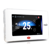
Introduction
The pGDx 4.3 inch graphic terminal is part of the family of touchscreen terminals designed
to simplify user interface with the pCO sistema family controllers. The electronic technology
used and the new 65K colour display means high quality images and advanced functions
are available for a superior appearance. The touchscreen panel moreover makes interaction
between the user and the unit much easier by simplifying navigation between the various
screens.
Part numbers
P/N Description Resolution
PGR04****A*** 1 RJ12 telephone connector 480x272
PGR04****B*** 1 485 port
1 24 Vdc power connector
1 optional keypad connector
PGR04****C*** 1 optically-isolated 485 port
1 24 Vdc power connector
1 optional keypad connector
1 Ethernet port
PGR04****E*** 1 24 Vdc power connector
1 Ethernet port
Packaging contents
pGDx; power supply and RS485 connectors (only on models where featured); fastening
screws; technical leaet.
Installation warnings
For correct installation contact a qualied installer.
Do not install the terminals in environments with the following characteristics:
• relative humidity greater than the value specied in the technical specications;
• with built-in temperature/humidity sensor, it is recommended to:
– only use faceplates tted ventilation openings
– install the display away from air streams coming from heating/cooling systems
– if installed vertically, position the probe at the bottom of the display
• strong vibrations or knocks;
• exposure to aggressive and polluting atmospheres (e.g.: sulphur and ammonia fumes, salt
spray, smoke) so as to avoid corrosion and/or oxidation;
• strong magnetic and/or radio frequency interference (therefore avoid installing the units
near transmitting antennae);
• exposure to direct sunlight or the elements in general;
• large and rapid uctuations in the room temperature;
• environments where explosives or mixes of ammable gases are present.
Devono essere rispettate le seguenti prescrizioni:
• only use shielded cables for Ethernet and RS485 communication networks;
• power supply voltages other than those specied may seriously damage the system;
• use cable ends suitable for the corresponding terminals. Loosen each screw and insert the
cable ends, then tighten the screws. When the operation is completed, slightly tug the cables
to check they are suciently tight;
• do not open the product when powered;
• operation at low temperatures may cause a noticeable decline in the response speed of the
display. This should be considered normal and does not indicate a malfunction.
• for one correct installation of IP65 models be safe of a 0,4 Nm screws tightening and a
correct assembly of the gasket.
• avoid any contact of the product with live parts.
• be sure that cables are accurately xed in order to avoid contact with live parts in case of
their accidentally disconnection.
Meaning of the colours on the notification bar
At power-on, the notication bar briey shows a blue signal to indicate the start of the
boot phase. The subsequent signals are then managed by the application program
developed using c.touch.
HMI Runtime and/or application update
Copy the update package (.ZIP le) containing
the runtime or application, or both, depending
on the options selected when generating
the “Update package” using c.touch, to a USB
pendrive and then plug the pendrive into the
pGDX and hold the pGDX terminal screen
for a few seconds until the shortcut menu is
:(displayed (see the gure on the side
Select “Update…” to
start the Runtime and/
or application update
procedure. The update
utility will start and the
following window will be
:displayed
Then follow
the guided
procedure,
selecting the le
saved on the USB
pen drive
System settings
Touch and hold the pGDX terminal screen for a few
seconds until the shortcut menu is displayed (see the
gure below). Select “Show system settings”; the main
conguration program screen will be displayed (gure
:(on the side
Below is a list of the functions relating to the dierent menu items:
Language Set the system language (not the c.touch application)
System
Contains information on the pGDX: BSP version, Memory, Timers and temperature / humidity
sensor (if featured)
Logs Download the system log les
Date & Time Set pGDX date and time using the automatic or manual procedure
Network
Show current system IP data (address, subnet, Gateway, DHCP, DNS) and access the Ethernet port
conguration menu
Services Start/stop various pGDX system services (Modbus server port, pGDX network address,…)
Management Update the dierent pGDX BSP partitions (CongOS, MainOS, Bootloader, Splash image, etc.…)
Display Set brightness, backlight timeout and screen orientation
Restart Restart the system
Authentication Set the password used to access the system
EXIT Exit the menu
Frame code
PGTA**F[T,H][0,1]*
Code PGTA00SM40
Code PGTA00RM40
Flat cable passage
only in case)
(of external keypad
Important:
keep the at cable
isolated from the
metal panel
Frame code
PGTA**F[W,B][0,1]*
Frame code
PGTA**F[W,B][0,1]*
Wall box
standard 503/GIRA
Note:
can only be used
with models
PG*******[B,E]***
Note:
Do not run power
cables inside the
ush-mount box