+050001895 - rel. 1.2 - 02.04.2019
Terminale utente pGDx Touch 4.3” -
User terminal pGD Touch 4.3”
pGDx
Introduzione
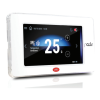
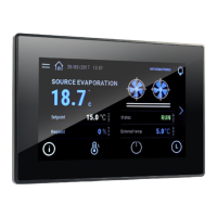
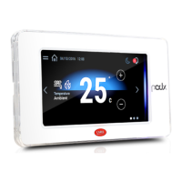
Il terminale grafico pGDx da 4.3 pollici appartiene alla famiglia di terminali touch screen
pensata per rendere semplice e intuitivo l’interfacciamento dell’utente con i controlli della
famiglia pCO Sistema. La tecnologia elettronica utilizzata e il display a 65K colori permettono
di gestire immagini di alta qualità e funzionalità avanzate per ottenere un elevato standard
estetico. Il terminale touch screen, inoltre, facilita l’interazione uomo-macchina rendendo,
di fatto, più facile la navigazione tra le varie schermate. A seconda dei modelli, sono possibili
diverse installazioni: a pannello, sia frontale che da retro, a muro oppure ad incasso. In ogni
caso è consentito sia l’orientamento orizzontale che verticale.
Codici modelli
Codice
N. porte
RS485
N. porte
ETH
Connettività
Wi-Fi
N. porte
RJ12
Connettore
Alimentatore
PGR04****A*** - - - 1 -
PGR04****B*** 1 - - - 1
PGR04****C*** 1 1 - - 1
PGR04****R*** 1 1
ü
- 1
PGR04****W*** 1 -
ü
- 1
PG[B,R]04****E*** - 1 - - 1
PG[B,R]04****H*** - 1
ü
- 1
Contenuto confezione
pGDx; connettori alimentazione e RS485 (solo nei modelli che lo prevedono); viti di fissaggio;
foglio istruzioni, antenna Wi-Fi (solo nei modelli che la prevedono, PG*04***D[H,R,W]***).
Sono esclusi invece: placchetta, alimentatore PGTA00TRX0 e scatole per il montaggio a
muro.
Avvertenze per l’installazione
Per una installazione a regola d’arte rivolgersi ad installatori abilitati. Evitare il montaggio dei
terminali in ambienti che presentino le seguenti caratteristiche:
• umidità relativa maggiore di quanto indicato nelle specifiche tecniche;
• forti vibrazioni o urti;
• esposizione ad atmosfere aggressive ed inquinanti (es.: gas solforici e ammoniacali,
nebbie saline, fumi) con conseguente corrosione e/o ossidazione;
• elevate interferenze magnetiche e/o radiofrequenze (evitare quindi l’installazione delle
macchine vicino ad antenne trasmittenti);
• esposizione all’irraggiamento solare diretto e agli agenti atmosferici in genere;
• ampie e rapide fluttuazioni della temperatura ambiente;
• ambienti ove sono presenti esplosivi o miscele di gas infiammabili.
Devono essere rispettate le seguenti prescrizioni:
• con sonda temperatura/umidità a bordo si raccomanda di:
– utilizzare solo cornici dotate di foro di aerazione
– installare il display lontano dai flussi d’aria proveniente da fonti di calore/
raffrescamento
– se installato in verticale, posizionare la sonda nella parte inferiore del display
• per le reti di comunicazione Ethernet e RS485 utilizzare esclusivamente cavi schermati;
• una tensione di alimentazione elettrica diversa da quella prescritta può danneggiare
seriamente il sistema;
• utilizzare capicorda adatti per i morsetti in uso. Allentare ogni vite ed inserirvi i capicorda,
quindi serrare le viti. Ad operazione ultimata tirare leggermente i cavi per verificarne il
corretto serraggio;
• nei modelli con antenna Wi-Fi esterna mantenere almeno un isolamento principale
(500 Vac secondo la IEC 60730-1) tra il connettore RP-SMA e la terra di protezione;
• non aprire il prodotto quando è alimentato;
• l’uso a temperature particolarmente basse può causare una visibile diminuzione
della velocità di risposta del display. Questo è da ritenersi normale e non è indice di
malfunzionamento.
• per una corretta installazione dei modelli IP65 assicurarsi un serraggio delle viti con
coppia 0,4 Nm e il corretto assemblaggio della guarnizione.
• evitare il contatto del prodotto con parti a tensioni pericolose.
• assicurarsi che i cavi siano opportunamente fissati in modo da evitare il contatto con
parti a tensioni pericolose nel caso di loro accidentale disconnessione.
Signicato colori notication bar
All’accensione la notification bar esegue una breve segnalazione di color blu per indicare
l’avvio della fase di boot. Le seguenti segnalazioni sono poi gestite dal programma
applicativo realizzato con c.touch.
Aggiornamento HMI Runtime e/o applicazione
1. Copiare il pacchetto di aggiornamento (file .ZIP) contenente
il runtime o l’applicazione, oppure entrambi, a seconda
delle opzioni scelte al momento della generazione di
“Update package” con c.touch, in una chiavetta USB e
successivamente collegare la chiavetta al pGDx. Tenere
premuto il dito sullo schermo del terminale pGDx per alcuni
secondi fino a che il menu contestuale sarà visualizzato,
disabilitabile lato applicativo (Fig. a lato):
2. Selezionare
“Update…” per
avviare la procedura
di aggiornamento
Runtime e/o
applicazione. L’utility
per l’aggiornamento si
avvierà ed apparirà la
seguente finestra:
3. Seguire quindi la
procedura guidata
selezionando il
file inserito nella
chiavetta USB e
premendo il tasto
next per conferma.
Impostazioni di sistema
Tenere premuto il dito sullo schermo del
terminale pGDx per alcuni secondi fino a
che il menu contestuale sarà visualizzato
(fig. sotto), Selezionare “Show system
settings”, apparirà la schermata principale
del programma di configurazione (fig a
lato):
Di seguito elencate le funzioni presenti nelle differenti voci del menù:
Language Impostazione della lingua di sistema (non dell’applicazione c.touch)
System
Contiene informazioni su pGDx: Versione BSP, Memoria, Timers e
sensore tempearatura / umidità (se presente)
Logs Permette di scaricare i file di log del sistema
Date & Time
Permette si settare data e ora di pGDx attraverso procedura
automatica o manuale
Network
Mostra gli attuali dati IP del sistema (indirizzo, subnet, Gateway,
DHCP, DNS) e permette di accedere al menu di configurazione della
porta Ethernet e dell’interfaccia Wi Fi
Services
Permette di accendere/spegnere diversi servizi di sistema (Modbus
server port, indirizzo pGDx nella rete,…)
Management
Permette di aggiornare le diverse partizioni BSP di pGDx (ConfigOS,
MainOS, Bootloader, Splash image, etc…)
Display
Permette di impostare luminosità, backlight timeout, orientamento
dello schermo e calibrazione del touch panel
Restart Lancia un riavvio del sistema
Authentication Permette di impostare password per accesso
EXIT Permette uscire dal menù
Dimensioni (mm) / Dimensions (mm)
151,5
87,7
8,9
133,8
125,7
67,5
33,1
43,9
116,6
84,3
133,8
42
31,6
4
RIGHT
WRONG
31,9
151,7
133,8
87,8
23
57,3
83,5
57,3
83,5
41,9
45,9
RIGHT side connection CHI/DE STANDARD
RIGHT side connection STANDARD 503
LEFT side connection (Ethernet version) STANDARD 503
LEFT side connection CHI/DE STANDARD
63,1
54,2
150,8
86,9
133,8
148,3
82,8
to remove for plasterboard installation
to remove for plasterboard installation
134
Ø 4
34.5
dima di foratura
drilling template
127x69 mm
Fig. 1
Installazione e montaggio (mm) /
Assembly and installation (mm)
Introduction
The pGDx 4.3 inch graphic terminal is part of the family of touchscreen terminals designed
to simplify user interface with the pCO sistema family controllers. The electronic technology
used and the new 65K colour display means high quality images and advanced functions
are available for a superior appearance. The touchscreen panel moreover makes interaction
between the user and the unit much easier by simplifying navigation between the various
screens. Different types of installation are available, depending on the model: front or
back panel, wall surface or flush-mount. In any case, the device can be mounted either
horizontally or vertically.
Part numbers
Codice
No. RS485
ports
No. ETH
ports
Wi-Fi
connectivity
No. RJ12
ports
Power supply
port
PGR04****A*** - - - 1 -
PGR04****B*** 1 - - - 1
PGR04****C*** 1 1 - - 1
PGR04****R*** 1 1
ü
- 1
PGR04****W*** 1 -
ü
- 1
PG[B,R]04****E*** - 1 - - 1
PG[B,R]04****H*** - 1
ü
- 1
Packaging contents
pGDx; power supply and RS485 connectors (only on models where featured); fastening
screws; technical leaflet, Wi-Fi antenna (only for models where fitted, PG*04***D[H,R,W]***).
Not included: frame, PGTA00TRX0 power supply and wall mounting boxes
.
Installation warnings
For correct installation contact a qualified installer.
Do not install the terminals in environments with the following characteristics:
• relative humidity greater than the value specified in the technical specifications;
• strong vibrations or knocks;
• exposure to aggressive and polluting atmospheres (e.g.: sulphur and ammonia fumes,
salt spray, smoke) so as to avoid corrosion and/or oxidation;
• strong magnetic and/or radio frequency interference (therefore avoid installing the units
near transmitting antennae);
• exposure to direct sunlight or the elements in general;
• large and rapid fluctuations in the room temperature;
• environments where explosives or mixes of flammable gases are present.
Devono essere rispettate le seguenti prescrizioni:
• with built-in temperature/humidity sensor, it is recommended to:
– only use faceplates fitted ventilation openings
– install the display away from air streams coming from heating/cooling systems
– if installed vertically, position the probe at the bottom of the display
• only use shielded cables for Ethernet and RS485 communication networks;
• power supply voltages other than those specified may seriously damage the system;
• use cable ends suitable for the corresponding terminals. Loosen each screw and insert the
cable ends, then tighten the screws. When the operation is completed, slightly tug the cables
to check they are sufficiently tight;
• in models with an external WiFi antenna, ensure at least basic insulation (500 Vac
according to IEC 60730-1) between the RP-SMA connector and the protective earth;
• do not open the product when powered;
• operation at low temperatures may cause a noticeable decline in the response speed of the
display. This should be considered normal and does not indicate a malfunction.
• for one correct installation of IP65 models be safe of a 0,4 Nm screws tightening and a
correct assembly of the gasket.
• avoid any contact of the product with live parts.
• be sure that cables are accurately fixed in order to avoid contact with live parts in case of
their accidentally disconnection.
Meaning of the colours on the notication bar
At power-on, the notification bar briefly shows a blue signal to indicate the start of the
boot phase. The subsequent signals are then managed by the application program
developed using c.touch.
HMI Runtime and/or application update
1. Copy the update package (.ZIP file) containing the runtime
or application, or both, depending on the options selected
when generating the “Update package” using c.touch, to a
USB pendrive and then plug the pendrive into the pGDx and
hold the pGDx terminal screen for a few seconds until the
shortcut menu is displayed, disableable application side (see
the figure on the side):
2. Select “Update…” to
start the Runtime and/
or application update
procedure. The update
utility will start and the
following window will
be displayed:
3. Then follow the
guided procedure,
selecting the file
saved on the USB
pen drive and
clicking the next
button to confirm.
System settings
Touch and hold the pGDx terminal screen
for a few seconds until the shortcut
menu is displayed (see the figure below).
Select “Show system settings”; the main
configuration program screen will be
displayed (figure on the side):
Below is a list of the functions relating to the different menu items:
Language Set the system language (not the c.touch application)
System
Contains information on the pGDx: BSP version, Memory, Timers
and temperature / humidity sensor (if featured)
Logs Download the system log files
Date & Time Set pGDx date and time using the automatic or manual procedure
Network
Show current system IP data (address, subnet, Gateway, DHCP, DNS)
and access the Ethernet and WiFi interface
Services
Start/stop various system services (Modbus server port, pGDx
network address,…)
Management
Update the different pGDx BSP partitions (ConfigOS, MainOS,
Bootloader, Splash image, etc.…)
Display
Set brightness, backlight timeout, screen orientation and touch
panel calibration
Restart Restart the system
Authentication Set the password used to access
EXIT Exit the menu
Frontale / Frontal
127 mm
Ø 4
134 mm
34,5 mm
69 mm
Fig.3a
Retro / Back
118 mm
40
134 mm
86 mm
5
5
34,5 mm
policarbonate
Fig.3b
Muro incasso Wall mounting
Fig.3c
Muro sbalzo Wall surface
Fig.3d
Passaggio cavo at
(solo in caso
di tastiera esterna)
Flat cable passage
(only in case
of external keypad)
Codice placchetta
Frame code:
PGTA**F[T,H][0,1]*
Codice placchetta
Frame code:
PGTA**F[T,H][0,1]*
Nota:
Non convogliare
cavi di potenza
all’interno dela
scatola da incasso
Note:
Do not run power
cables inside the
ush-mount box
Importante:
mantenere
il flat isolato
dal pannello
metallico
Important:
keep the at cable
isolated from the
metal panel
Nota:
utilizzabile solo
con modelli
PG*******[B,E,W,H]***
Note:
can only be used
with models
PG*******[B,E,W,H]***
Scatola a muro / Wall box
standard ITA/CHN/DEU/USA
Codice placchetta
Frame code:
PGTA**F[B,W][0,1]*
Coppia di serraggio 0.4 Nm
Tightening torque 0.4 Nm
Accessorio per installazione a muro a sbalzo (rif. figura 3d) - codice: PGTA00SM40
Accessory for wall surface installation (ref. Figure 3d) - P/N: PGTA00SM40
Accessorio per installazione a muro ad incasso (rif. figura 3c) - codice: PGTA00RM40
Accessory for ush-mounted wall installation (ref. Figure 3c) - P/N: PGTA00RM40
Non fornita da Carel
Not supplied by Carel