CAREL Industries HQs
Via dell’Industria, 11 - 35020 Brugine - Padova (Italy)
Tel. (+39) 0499716611 – Fax (+39) 0499716600 – www.carel.com – e-mail: carel@carel.com
+050001895 - rel. 1.2 - 02.04.2019
CAREL si riserva la possibilità di apportare modifiche o cambiamenti ai propri prodotti senza alcun preavviso.
CAREL INDUSTRIES reserves the right to modify the features of its products without prior notice.
Caratteristiche tecniche
Display
Tipo LCD TFT
Risoluzione 480x272 Wide
Area attiva del display 4.3” diagonale
Colori 65 K
Retro-illuminazione LCD - Lifetime 20 khrs @ 25 °C
Regolazione luminosità Si - auto spegnimento di default dopo 15 min
Angolo visivo (CR ≥10) Alto/Basso (40/50 deg.) - Sinistra/Destra (50/50 deg.)
Contrasto (tipico) 350 (Φ=0°)
Luminosità (tipico) 200 cd/m
2
Interfaccia utente
Touchscreen Resistivo
Indicatori LED sistema Notification bar a 8 colori
Interfacce
Porta Ethernet Auto-MDIX 10/100 Mbit - RJ45 femmina
Cavo STP CAT 5 Lmax = 100m
Wi Fi IEEE 802.11 b/g/n - STATION/ACCESS POINT mode
Antenna integrata/esterna a seconda dei modelli
Max Transmit Power = 17dBm
Remotazione antenna esterna Lmax = 2 m
Connettore antenna esterna RP-SMA femmina
(per modelli PG*04***D[H,R,W]***)
Porta USB () Host interface 2.0 - micro USB -B - 150 mA max (non
utilizzare per ricaricare dispositivi) Lmax = 1m
Porta Seriale con connettore RJ12 RS485 max 115,2 Kb/s
Cavo telefonico a 6 fili Lmax = 2m
Porta Seriale con morsetto a
vite ()
RS485 max 115,2 Kb/s
Connettore sconnettibile a vite passo 3,81mm
Cavo schermato AWG 20-22 a coppie ritorte per ±
Lmax = 500m - coppia serraggio 0,25Nm (2.2lbf x in)
Sonda temperatura / umidità 0...50 °C / 20...80% rH
0...50 °C ±1 °C (in aria statica)
20...80% ±5% (in aria statica)
()
solo per manutenzione. La porta USB può essere danneggiato da ESD (Scariche
Elettrostatiche). Si consiglia di adottare le opportune precauzioni al fine di evitarne la rottura.
() optoisolata per modello PGR04****[C,R]***
Funzionalità
Grafica vettoriale Si, incluso supporto SVG 1.0
Oggetti dinamici Si Visibilità, posizione, rotazione
TrueType fonts Si
Multiprotocollo Si
Storico e trend Si. Limitato alla memoria della Flash memory
Multi-lingue Si, con impostazione della lingua run-time e limitato
solo dalla memoria disponibile
Recipes (ricette) Si. Limitato alla memoria della Flash memory
Allarmi Si
Lista event Si
Passwords Si
Real Time Clock () Si, con batteria di back-up
Screen saver Si
Buzzer () “Beep” alla pressione del touch (configurabile)
() solo per i modelli che lo prevedono
Elettriche
Alimentazione PGR04****A*** Alimentazione fornita da pCO tramite connettore RJ12
(verificare che l’alimentazione fornita dal controllo sia
compatibile con i consumi di PGDx) - Lmax = 2 m
Alimentazione
PG*04****[B,C,E,H,R,W]***
24Vdc fornita tramite accessorio PGTA00TRX0 Lmax =
50 m (--) - sezione cavo AWG 12-20
coppia serraggio 0.8 Nm (7 lbf x in)
Massima potenza assorbita 7W, eccezione PGR04****A*** = 3W
Fusibile Automatico
Peso Approx 250 g
Batteria Non ricaricabile al litio mod BR1225
Classe e struttura del software A
Scopo del dispositivo dispositivo di comando di funzionamento
Costruzione del controllo montaggio indipendente (PG*04***[F,T]****)
incorporato (PG*04***[R,D,W]****)
Tipo di azione automatica azione tipo 1
Resistenza al calore e al fuoco Cat. D
Immunità contro le sovratensioni Cat. III
Classe isolamento Classe III
() Per i modelli PGR04***[F,T]****. Per il collegamento di -Vdc a terra seguire le
prescrizioni degli schemi di collegamento
() Per i modelli PG*04***W**** installati ad incasso l’accessorio PGTA00TRX0 deve essere
installato in una scatola dedicata
() Range di alimentazione: 24 Vdc ± 10%
Condizioni ambientali
Temperatura di lavoro PG*04***[T,D]****: -20T60 °C
PG*04***[F,R,W]****: 0T50 °C
Temperatura di immagazzinam. PG*04*******: -30T70 °C
Umidità relativa massima di lavoro
e immagazzinamento
85% @ 40 °C non-condensante
Grado di protezione PG*04***T****: IP65, NEMA Type 1 (frontale)
se accoppiato all’accessorio PGTA**F [B,W][0,1]* (cornice)
PG*04***[D,F,R,W]****: IP20, NEMA Type 1 (frontale)
Grado di inquinamento 3
Technical specications
Display
Type LCD TFT
Resolution 480x272 Wide
Active display area 4.3” diagonal
Colours 65 K
Backlighting LCD - Lifetime 20 khrs @ 25 °C
Brightness control Yes - auto-off by default after 15 min
Visual angle (CR ≥10) Up/Down (40/50 deg.) - Left/Right (50/50 deg.)
Contrast (typical) 350 (Φ=0°)
Brightness (typical) 200 cd/m
2
User interface
Touchscreen Resistive
System signal LEDs 8-colour notification bar
Interfaces
Ethernet port Auto-MDIX 10/100 Mbit - RJ45 female
STP CAT 5 cable Lmax = 100 m
Wi Fi IEEE 802.11 b/g/n - STATION/ACCESS POINT mode
Built-in/external antenna based on model
Max Transmit Power = 17dBm
External antenna remote mounting Lmax = 2 m
External antenna connector RP-SMA female
(for models PG*04***D[H,R,W]***)
USB port () Host interface 2.0 - micro USB -B - 150 mA max
(do not use to charge devices) - Lmax = 1m
Serial port with RJ12 connector RS485 max 115.2 Kb/s
6-wire telephone cable Lmax = 2m
Serial port with screw terminal () RS485 max 115,2 Kb/s
Removable screw connector 3,81mm pitch
Shielded twisted pair cable AWG 20-22 for ±
Lmax = 500m - tightening torque 0.25Nm (2.2lbf x in)
Temperature / humidity probe 0 to 50 °C / 20 to 80% rH
0 to 50 °C ±1 °C (static air)
20 to 80% ±5% (static air)
()
only for service. The USB port can be damaged by ESD (Electro-Static Discharges).
It’s recommended to adopt appropriate precautions in order to avoid failures.
() opto-isolated for model PGR04****[C,R]***
Functions
Vector graphics Yes, includes SVG 1.0 support
Dynamic objects Yes Visibility, position, rotation
TrueType fonts Yes
Multi-protocol Yes
Logs and trends Yes. Limited to Flash memory capacity
Multilanguage Yes, run-time language setting and limited only by
available memory
Recipes Yes. Limited to Flash memory capacity
Alarms Yes
Event list Yes
Passwords Yes
Real Time Clock () Yes, with backup battery
Screen saver Yes
Buzzer () “Beep” when pressing the touchscreen (settable)
() only on models where featured
Electrical
PGR04****A*** power supply Power supply from pCO via RJ12 telephone connector
(check that the power supplied by the controller is
compatible with PGDx power consumption)
PG*04****[B,C,E,H,R,W]***power
supply
24Vdc supplied by PGTA00TRX0 accessory
Lmax = 50 m(--)- cable cross section AWG 12-20
tightening torque 0.8 Nm (7 lbf x in)
Max Power Absorption 7W, exception PGR04****A*** = 3W
Fuse Automatic
Weight Approx. 250 g
Battery Non-rechargeable lithium model BR1225
Software class and structure A
Purpose of control operation control
Controller construction independently mounted control (PG*04***[F,T]****)
incorporated control (PG*04***[R,D,W]****)
Type of automatic action type 1 action
Heat and fire resistance Cat. D
Overvoltage category Cat. III
Insulation class Class III
() For models PGR04***[F,T]****. To connect -Vdc to earth follow the instructions on the
connection diagrams
() For models– for flush mounting the PGTA00TRX0 accessory must be installed in a
dedicated box
() Power supply range: 24 Vdc ± 10%
Environmental conditions
Operating temperature PG*04***[T,D]****: -20T60 °C
PG*04***[F,R,W]****: 0T50 °C
Storage temperature PG*04*******: -30T70 °C
Maximum operating and storage
relative humidity
85% @ 40 °C non-condensing
Ingress protection PG*04***T****: IP65, NEMA Type 1 (front)
if coupled with PGTA**F [B,W][0,1]* (frame)
PG*04***[D,F,R,W]****: IP20, NEMA Type 1 (front)
Pollution degree 3
Collegamenti elettrici /
Network connection:
4 10 6 3 92 1
75
GND
RX/TX +
+
–
+
–
RX/TX –
GND
RX/TX +
RX/TX –
8
Fig.4
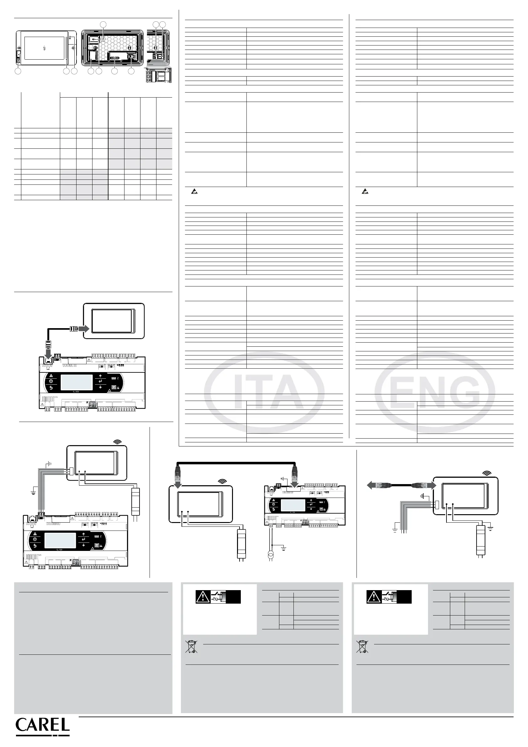
Mounting Connectivity
Description
PG*04***[F/T]****
Front Panel
Mounting
PG*04***D****
Rear Panel
Mounting
PG*04***W****
Wall Mounting
PGR04****A***
PGR04****[B/W]***
PGR04****[C/R]***
PG04****[E/H]***
1 MicroUSB rear
(*)
2 MicroUSB front
3
external keypad
connector
4
temperature and
humidity probe (6)
(option)
5
Wi-Fi antenna SMA
connector (RP-SMA)
6 Ethernet port
7 RS485 port
8 power supply port
9
RJ12 connector
(power/RS485)
10 notication bar
Tab. 2
Se la porta RS485 è usata come pLAN (Modbus over pLAN) o display port: NON collegare
le resistenze di terminazione da 120 ohm sul primo e sull’ultimo dispositivo della rete in
quanto la porta RS485 è di tipo HW slave, il numero massimo di dispositivi collegabili nella
rete è 32 e la lunghezza massima della rete è 500m.
() Verificare periodicamente la corretta pulizia dei fori di areazione della sonda.
(*) Escluso modello PGR04***FA***.
If the RS485 port is used as pLAN (Modbus over pLAN) or display port: DO NOT connect the
120 Ohms terminal resistors into the first and the last devices of the RS485 network, this is
because the RS485 port is HW Slave type. The maximum number of devices which can be
connected in the network is 32, and the maximum lenght of it is 500meters.
(6) Periodically check that the probe ventilation holes are clean.
(*) Excepted PGR04***FA*** model.
Schema per collegamento a pCO/c.pCO
Connection to
pCO/c.pCO
IMPORTANT WARNINGS
The CAREL product is a state-of-the-art product, whose operation is specified in the technical
documentation supplied with the product or can be downloaded, even prior to purchase, from the
website www.carel.com. - The client (builder, developer or installer of the final equipment) assumes
every responsibility and risk relating to the phase of configuration the product in order to reach the
expected results in relation to the specific final installation and/or equipment. The lack of such phase
of study, which is requested/indicated in the user manual, can cause the final product to malfunction
of which CAREL can not be held responsible. The final client must use the product only in the manner
described in the documentation related to the product itself. The liability of CAREL in relation to its own
product is regulated by CAREL’s general contract conditions edited on the website www.carel.com and/
or by specific agreements with clients.
AVVERTENZE IMPORTANTI
Il prodotto CAREL è un prodotto avanzato, il cui funzionamento è specificato nella documentazione
tecnica fornita col prodotto o scaricabile, anche anteriormente all’acquisto, dal sito internet www.
carel.com. Il cliente (costruttore, progettista o installatore dell’equipaggiamento finale) si assume ogni
responsabilità e rischio in relazione alla fase di configurazione del prodotto per il raggiungimento dei
risultati previsti in relazione all’installazione e/o equipaggiamento finale specifico. La mancanza di tale
fase di studio, la quale è richiesta/indicata nel manuale d’uso, può generare malfunzionamenti nei
prodotti finali di cui CAREL non potrà essere ritenuta responsabile. Il cliente finale deve usare il prodotto
solo nelle modalità descritte nella documentazione relativa al prodotto stesso. La responsabilità di
CAREL in relazione al proprio prodotto è regolata dalle condizioni generali di contratto CAREL editate
nel sito www.carel.com e/o da specifici accordi con i clienti.
Disposal of the product
The appliance (or the product) must be disposed of separately in compliance with the local
standards in force on waste disposal.
Smaltimento del prodotto
L’apparecchiatura (o il prodotto) deve essere oggetto di raccolta separata in conformità alle
vigenti normative locali in materia di smaltimento.
Regole per lo smaltimento / Disposal regulations
• Non smaltire il prodotto come rifiuto solido urbano ma smaltirlo negli appositi
centri di raccolta.
• Il prodotto contiene una batteria, è necessario disalimentare il dispositivo e
rimuovere il coperchio posteriore, quindi toglierla prima di procedere al suo
smaltimento.
• Un uso improprio o uno smaltimento non corretto potrebbe avere effetti negativi
sulla salute umana e sull’ambiente.
• Per lo smaltimento vanno utilizzati i sistemi di raccolta pubblici o privati previsti dalle
leggi locali.
• In caso di smaltimento abusivo dei rifiuti elettrici ed elettronici sono previste
sanzioni stabilite dalle vigenti normative locali in materia di smaltimento.
•
Do not dispose of the product as solid municipal waste; take it to the proper collection
centres.
•
The product contains a battery, power down the device, remove the rear cover and
must be removed, before proceeding with disposal.
•
Improper use or disposal could have a negative effect on human health and the
environment.
•
Public or private waste collection systems defined by local legislation must be used for
its disposal.
•
in the event of illegal disposal of waste electrical and electronic equipment, penalties
have been established by the current local laws regarding disposal.
Standards
Safety UL UL60730-1
sch. CB IEC60730-1
EMC CE EN61000-6-1 / EN61000-6-2
EN61000-6-3 / EN61000-6-4
EN55014-1 / EN55014-2
Radio Red EN301489-1/EN301489-17
EN300328
FCC Part.15 Subpart.B
Normative
Sicurezza UL UL60730-1
sch. CB IEC60730-1
EMC CE EN61000-6-1 / EN61000-6-2
EN61000-6-3 / EN61000-6-4
EN55014-1 / EN55014-2
Radio Red EN301489-1/EN301489-17
EN300328
FCC Part.15 Subpart.B
+ –
PGDx
to pCO/c.pCO
Ethernet
Wi Fi
L N
+ –
PGTA00TRX0
230 Vac
24 Vdc
to c.pCO
PGDx
C1
NO1
NO2
NO3
C1
C4
NO4
NO5
NO6
C4
C7
NO7
C7
NO8
C8
NC8
G
G0
U1
U2
U3
GND
+VDC
U4
GND
U5
GND
VG
VG0
Y1
Y2
Y3
Y4
ID1
ID2
ID3
ID4
ID5
ID6
ID7
ID8
IDC1
J1
J2
J3
J4
J5
J14
J10
J13
J12
J15
drac SMBdrac suBdleiF
4 3 2 1
Tx/Rx
J11 pLAN
GND
J25 BMS2
Tx/Rx
GND
Tx/Rx
GND
J26 FBus2
+Vterm
GND
+5VREF
J24
+
XXXXXXXXXXXX
Fix: cavo telefonico RJ12
Fix: RJ12 telephone cable
pCO/c.pCO
S90CON*
Modelli con connettore RJ12
Models with RJ12 connector
Fig. 5
+ –
PGDx
C1
NO1
NO2
NO3
C1
C4
NO4
NO5
NO6
C4
C7
NO7
C7
NO8
C8
NC8
G
G0
U1
U2
U3
GND
+VDC
U4
GND
U5
GND
VG
VG0
Y1
Y2
Y3
Y4
ID1
ID2
ID3
ID4
ID5
ID6
ID7
ID8
IDC1
J1
J2
J3
J4
J5
J14
J10
J13
J12
J15
drac SMBdrac suBdleiF
4 3 2 1
Tx/Rx
J11 pLAN
GND
J25 BMS2
Tx/Rx
GND
Tx/Rx
GND
J26 FBus2
+Vterm
GND
+5VREF
J24
+
XXXXXXXXXXXX
pCO
c.pCO
Wi Fi
L N
+ –
PGTA00TRX0
230 Vac
24 Vdc
Modelli con morsetto a vite RS485/Wi Fi
Models with RS485/Wi Fi screw terminal
Fig. 6
Modelli con connettore Ethernet e morsetto a vite RS485/Wi Fi
Models with Ethernet connector and RS485/Wi Fi screw terminal
G G0
24 Vdc
230 Vac
C1
NO1
NO2
NO3
C1
C4
NO4
NO5
NO6
C4
C7
NO7
C7
NO8
C8
NC8
G
G0
U1
U2
U3
GND
+VDC
U4
GND
U5
GND
VG
VG0
Y1
Y2
Y3
Y4
ID1
ID2
ID3
ID4
ID5
ID6
ID7
ID8
IDC1
J1
J2
J3
J4 J5
J14
J10
J13
J12
J15
drac SMBdrac suBdleiF
4 3 2 1
Tx/Rx
J11 pLAN
GND
J25 BMS2
Tx/Rx
GND
Tx/Rx
GND
J26 FBus2
+Vterm
GND
+5VREF
J24
+
XXXXXXXXXXXX
c.pCO
+ –
Ethernet
Wi Fi
L N
+ –
PGTA00TRX0
230 Vac
24 Vdc
Modelli con connettore Ethernet/Wi Fi
Models with Ethernet/Wi Fi connector
Fig. 7
Fig. 8
NO POWER
& SIGNAL
CABLES
TOGETHER
READ CAREFULLY IN THE TEXT!
NO POWER
& SIGNAL
CABLES
TOGETHER
READ CAREFULLY IN THE TEXT!
Always keep the signal cables
and power cable in separate
conduits.
Mantenere sempre in canaline
separate i cavi di segnale
dai cavi di potenza.
 Loading...