Do you have a question about the Carel pGD Touch and is the answer not in the manual?
Guidelines for the proper disposal of WEEE according to EU directive.
Information on product warranty duration and quality system approval.
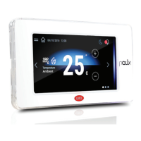
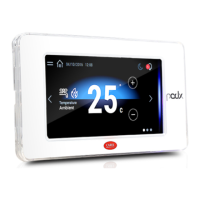
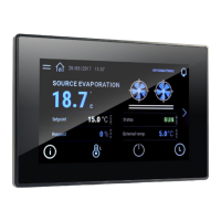
Overview of the PGD Touch terminal's capabilities, design, and programming environment.
Details the different PGD Touch models, including their screen sizes and communication ports.
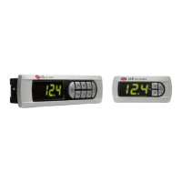
Lists and describes available accessories for the PGD Touch terminal.
Details the physical components and layout of the PGD Touch terminal.
Explains the meaning of the two-colour Signal LED indicator on the terminal.
Describes the function of the LEDs on the Ethernet ports for connection and activity status.
Details the functionality and use of the USB port for data transfer and programming.
Details the types of serial ports available on PGD Touch terminals and their configurations.
Explains the pinout and configuration of the DB9 connector used for serial communication.
Describes how to establish network connections between controllers using RS485 and Ethernet.
Provides guidelines and diagrams for setting up RS485 network connections.
Explains the configuration and usage of Ethernet networks for terminal connectivity.
Provides the physical dimensions of the PGD Touch terminals for installation planning.
Specifies the recommended environmental conditions for installing the PGD Touch terminal.
Details the drilling template dimensions and minimum clearances required for mounting.
Outlines the procedure for assembling the PGD Touch terminal into an electrical panel.
Explains how to load the application program onto the terminal via Ethernet or USB.
Details the methods for connecting the terminal to a computer for configuration.
Describes how to establish a direct connection between the computer and terminal using IP settings.
Explains how to connect the terminal to a network via DHCP for automatic IP assignment.
Outlines the process of copying or updating the application program using a USB drive.
Details how to access and configure basic terminal settings using the system setting tool.
Illustrates system terminal connection with pCO5+ controllers in an RS485 network.
Shows system and remote terminal connection configurations over RS485.
Presents alternative RS485 connection diagrams for system and remote terminals.
Illustrates network configurations for BACnet MS/TP connectivity.
Shows network diagrams for mixed RS485 and Ethernet connections.
Illustrates network diagrams for BACnet/IP or Modbus TCP/IP with Ethernet.
Provides detailed technical specifications for all PGD Touch terminal models.
Explains how to save and export data from the terminal to USB or SD card.
Describes methods for establishing remote connections to the PGD Touch terminal.
Details how to use the 1toolTE Windows Client for remote terminal access.
Explains how to use the 1toolTE ActiveX Client for remote terminal access via Internet Explorer.
| Display Type | Color TFT LCD |
|---|---|
| Touch Technology | Capacitive |
| Resolution | 800 x 480 pixels |
| Processor | Cortex A8 |
| Communication Ports | Ethernet, USB, RS-485 |
| Power Supply | 24 V DC |
| Protection Rating | IP65 |
| Display Size | 7 inches |