21
pGD Touch +030221540 rel. 1.1 - 21.01.2015
ENG
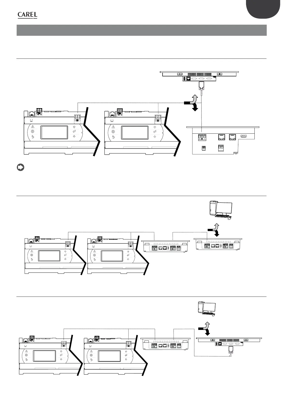
6. APPLICATION DIAGRAMS
For details on the earth connection, see the paragraph “Network connection between controllers”.
6.1 Diagram 1: system terminal and pCO5+ controllers in RS485 network
pGD Touch: 4,3”, 7”
1
8
1
8
J10
FieldBus card
BMS card
J11 pLAN
J25 BMS2
1
Tx/Rx
GND
J10
FieldBus card
BMS card
J11 pLAN
J25 BMS2
1
Tx/Rx
GND
Modbus RTU
pGD Touch: 10”, 13”
1
8
connessioni in alternativa/
alternative connections
Fig. 6.a
Note: the 10” and 13” terminals require a terminating resistor at the end of the line, as the RS485 port on the pGD Touch 10 and 13 is configured for
Master hardware.
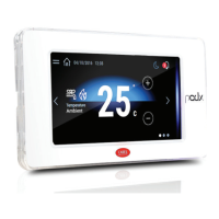
6.2 Diagram 2a: system terminal and remote terminal over RS485
1
8
1
8
G
G0
1
8
1
8
G
G0
PlantVisorPro
pGD Touch: 7”
pGD Touch: 4,3”, 7”
J10
FieldBus card
BMS card
J11 pLAN
J25 BMS2
1
Tx/Rx
GND
J10
FieldBus card
BMS card
J11 pLAN
J25 BMS2
1
Tx/Rx
GND
connessioni in alternativa/
alternative connections
Modbus RTU
Modbus RTU
A
B
Fig. 6.b
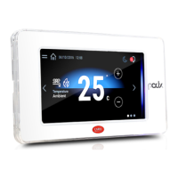
6.3 Diagram 2b: system terminal and remote terminal over RS485
1
8
1
8
G
G0
pGD Touch: 7”
J10
FieldBus card
BMS card
J11 pLAN
J25 BMS2
1
Tx/Rx
GND
J10
FieldBus card
BMS card
J11 pLAN
J25 BMS2
1
Tx/Rx
GND
pGD Touch: 10”, 13”
1
8
PlantVisorPro
connessioni in alternativa/
alternative connections
NOTA: max 2 terminali con porta con hardware master per rete RS485/
NOTE: max 2 terminals with port with master hardware for RS485 networ
Modbus RTU
Modbus RTU
A
B
Fig. 6.c