16
pGD Touch +030221540 rel. 1.1 - 21.01.2015
ENG
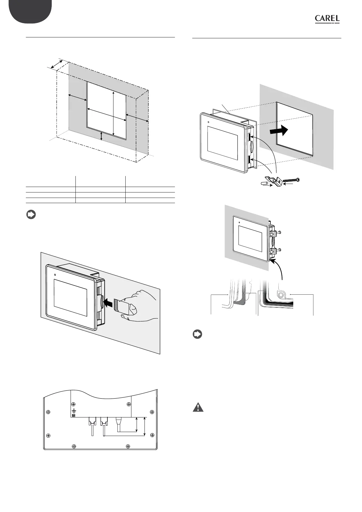
4.3.3 Drilling template and minimum distances
The drilling template used for assembly must have the dimensions
shown in the figure.
w
z
a
b
c
d
Fig. 4.b
Size w (mm) z (mm)
4,3” 136 96
7” 176 136
10” 276 (10.86”) 221 (8.7”)
13” 326 (12.83”) 256 (10.07”)
Tab. 4.c
Note: leave minimum clearance around the terminal (a, b, c, d) so
as to:
1. allow ventilation;
2. temporarily access the device to insert and remove a USB pendrive
or SD card;
Fig. 4.c
3. keep in mind the space occupied by cables and connectors
(distances in mm)
AUX
PLC PC/PRINTER ETHERNET USB
40
100
Fig. 4.d
4.4 Assembly
Make a rectangular opening as shown in the previous paragraph.
Procedure:
1. insert the gasket (see the figure for the 4.3” and 7” models);
2. place the terminal in the opening;
3. tighten all the screws on the fastening clips until the end of the nut
touches the panel.
1
3
2
Fig. 4.e
display
guarnizione lato liscio
flat side gasket
guarnizione lato a righe
striped side gasket
retro display
rear display
Fig. 4.f
Note:
• the thickness of the electrical panel sheet metal (or other material)
must be suitable to ensure safe and stable terminal assembly;
• the pressure exerted by the fastening clips must not deform the sheet
metal, so as to ensure the protection rating (IP) shown in the table of
technical specifications;
• insert the fastening clips so as to ensure uniform pressure of the
terminal on the panel and consequently the specified protection
rating (IP).
Important: front IP65 protection rating is only guaranteed if are
the following conditions have been met:
1. maximum deviation of the drilling template from the flat surface: ≤
0.5 mm;
2. electrical panel sheet metal thickness: 1.5 to 6 mm;
3. maximum roughness of the surface where the gasket is applied: ≤
120 μm.