12
pGD Touch +030221540 rel. 1.1 - 21.01.2015
ENG
3.3 Network connection between controllers
3.3.1 RS485 network
To improve the device’s immunity to electromagnetic disturbance, the serial
connection must use a shielded twisted pair cable, AWG 20-22, with capacitance
between wires < 90 pF/m, with two or three wires depending on the insulation
of the serial connection.
Rules for connecting together two devices:
• if at least one of the serial ports being connected together is optically-
isolated from its own power supply (functional insulation), a third wire is
required in the serial cable to act as a common reference for the two devices,
irrespective of whether the G0 terminals are connected;
• if the serial ports being connected together are both not optically-isolated,
and the G0 terminals on both devices are not connected together, a three-
wire cable is used; if the G0 terminals are connected together, a two-wire
cable is used.
If the RS485 port is used as Modbus/Carel master, a maximum of 255 devices can
be connected in the network, and the maximum network length is 500 m.
4.3” – 7” models
Do not connect the 120 1 terminating resistors on the first and last device in the
network, as the RS485 port has a slave hardware configuration.
Note:
• for network connection using BACnet MS/TP protocol, the pCO controllers
need to be fitted with the pCONet card (P/N PCO1000BA0) and the network
communication speed will be the maximum allowed by each device (Note: the
communication speed should be set to the same value on each device);
• pGD touch can manage just one protocol at any time, either BACnet TCP/IP or
BACnet IP
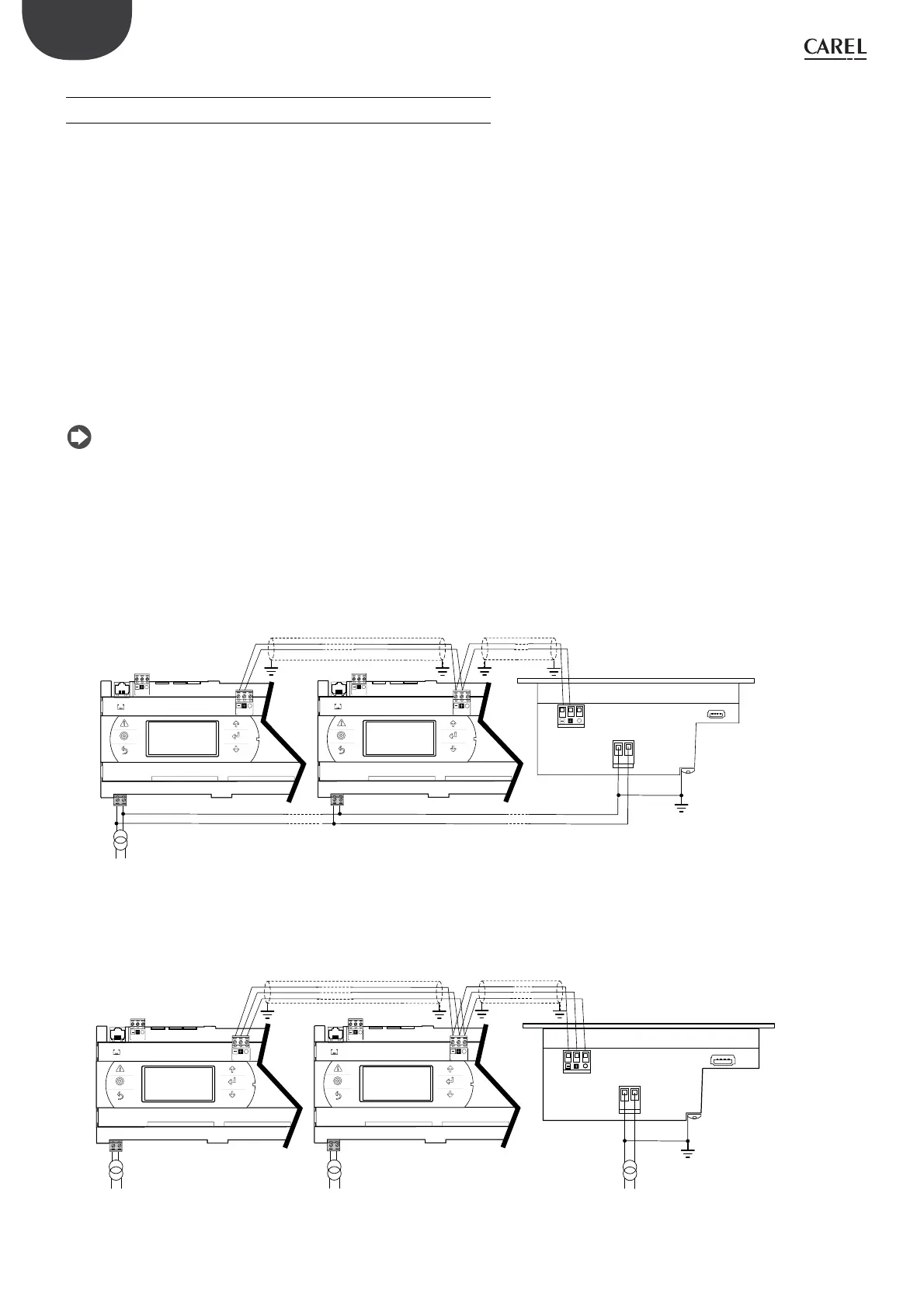
SERIAL PORTS THAT ARE NOT OPTICALLY-ISOLATED
Case 1: multiple devices connected in a serial network powered by the same
transformer; this is a typical application for a series of devices connected inside
the same electrical panel.
J10
FieldBus card
BMS card
J11 pLAN
J25 BMS2
1
J10
FieldBus card
BMS card
J11 pLAN
J25 BMS2
1
24 Vac
G
G0
G
G0
230 Vac
L
N
G
G0
Tx/Rx GND
Tx/Rx GND
Tx/Rx
GND
Tx/Rx
GND
Fig. 3.a
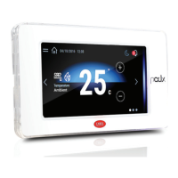
Case 2: multiple devices connected in a serial network powered by different
transformers (G0 not connected to earth); this is a typical application for a series
of devices that are installed in different electrical panels.
J10 J11 pLAN
J25 BMS2
1
J10 J11 pLAN
J25 BMS2
1
G
G0
G
G0
GG0
24 Vac
230 Vac
L
N
24 Vac
230 Vac
L
N
24 Vac
230 Vac
L
N
Tx/Rx
GND
Tx/Rx
GND
Tx/Rx
GND
Tx/Rx
GND
FieldBus card
BMS card
FieldBus card
BMS card
Fig. 3.b
pGD Touch:
4,3”: PGDT04000FS00
7”: PGDT07000FR00
pGD Touch:
4,3”: PGDT04000FS00
7”: PGDT07000FR00