11
pGD Touch +030221540 rel. 1.1 - 21.01.2015
ENG
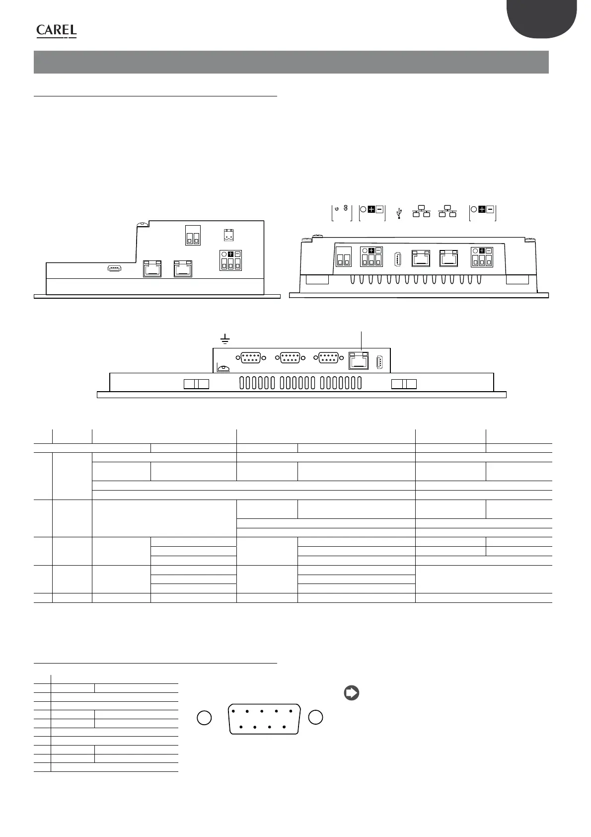
3. COMMUNICATION PORTS
3.1 Serial ports
The range of pGD Touch terminals features three types of serial ports:
• RS485 port with 3-pin plug-in connector, available on 4.3” and 7”
models;
• RS485, RS232, RS422 port selectable via software, with DB9 female
connector, programmable via software, available on 10” and 13”
models;
• Ethernet port, available on all models, to connect the terminal to
another terminal or a LAN.
The hardware features of the serial ports are shown below.
1
8
1
8
L
I
H
1
8
1
8
1
8
H
AUX PLC PC/PRINTER
USB
ETHERNET
LHIM
M
L
Q
G
G0
G
G0
eth 2 eth 1 serial 1serial 2
24 V~
GNDTx/Rx GNDTx/Rx
Fig. 3.a
Ref. Serial port 4,3 7 10 13
PGDT04000FS00 PGDT04000F020 PGDT07000FR00 PGDT07000F120 PGDT10000FR10 PGDT13000FR10
L RS485 1
Driver HW: RS485 slave Driver HW: RS485 slave Driver HW: RS485 slave(*)
not optically-
isolated
optically-isolated
not optically-
isolated
optically-isolated not optically-isolated
not optically-
isolated
Connector: 3-pin plug-in screw terminal, pitch 5.08 mm DB9 female connector
Bit rate: max 115 Kb/s Bit rate: max 115 Kb/s
M RS485 2 -
not optically-
isolated
not optically-isolated not optically-isolated
not optically-
isolated
Connector: 3-pin plug-in screw terminal, pitch 5.08 mm DB9 female connector
Bit rate: max 115 Kb/s Bit rate: max 115 Kb/s
H Ethernet 1 -
Internal switch
-
Internal switch - -
Auto MDIX 10/100 Mbit Auto MDIX 10/100 Mbit - -
Connector: RJ45 female Connector: RJ45 female Connector: RJ45 female
I Ethernet 2 -
Internal switch
-
Internal switch
-Auto MDIX 10/100 Mbit Auto MDIX 10/100 Mbit
Connector: RJ45 female Connector: RJ45 female
Q AUX - - - not active
Tab. 3.a
RS232, RS485, RS422 can be configured by software.
3.2 DB9 Connector
Pin Description
1
9
Fig. 3.b
Note: the DB9 female connector has a Slave hardware
configuration. When connecting the RS485 cable adapter
(accessory), fitted with polarisation resistors, it has a Master
hardware configuration.
RS232 RS422, RS485
1 GND
2-
3 TX CHA-
4 RX CHB-
5-
6 + 5 V output
7 CTS CHB+
8 RTS CHA+
9-
Tab. 3.b
The different number of ports available on each model, and the different
hardware and protocols selected for each port, define:
1. the network structure (see “Application diagrams”);
2. the maximum communication speed;
3. the maximum network length;
4. the maximum number of devices that can be connected.
4,3"
7"
10" - 13"