17
pGD Touch +030221540 rel. 1.1 - 21.01.2015
ENG
4.5.1 DC power supply
The connection diagram for the 10” and 13” models with direct current
power supply is shown below.
+24 V
0V
L
N
N
L
+V
-V
100-240 Vac
PGTA00TRF0
PGD10/PGD13
Rear panel
Fig. 4.j
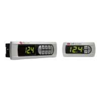
4.5.2 AC power supply
Use a safety transformer or power supply with separate windings that
ensures equivalent insulation as established by IEC 61558-2-6 and IEC
61558-2-17, and earth the terminal's metal casing and G0 (functional
connection). If the terminal is integrated into a class I device where
metallic parts may come into contact with dangerous voltages, a
protective earth connection is required, connecting the terminal’s metal
casing metal to the class I device earth connector.
Important: if the same power transformer is used for the terminal
and the corresponding control device, do not reverse the G0 and G
connections on the power terminals to avoid damaging the devices.
pGD Touch 4,3”, 7”
1
8
1
8
J10
FieldBus card
BMS card
J11 pLAN
J25 BMS2
1
Tx/Rx
GND
G
G0
24 Vac
230 Vac
FUSE
AC
Tx/Rx
GND
GG0
Fig. 4.k
4.5.3 Network connection between controllers
See paragraph 3.3.
4.5 Electrical connections
The type of power supply is shown in the following table.
pGD Touch Model Power supply
4,3” 24 Vac; 12…30 Vdc
7” 24 Vac; 12…30 Vdc
10” 24 Vdc, 18…30 Vdc
13” 24 Vdc, 18…30 Vdc
Tab. 4.d
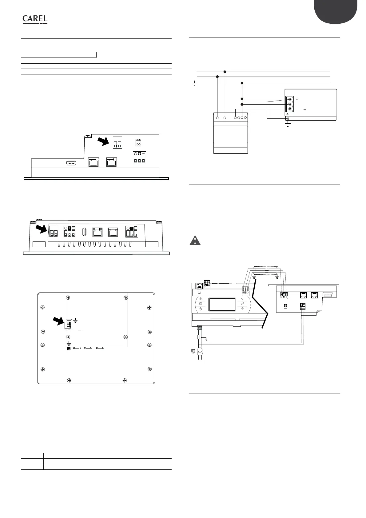
For models with DC power supply, make sure the power supply can
deliver the power required for correct operation of the device.
Make sure the polarity is correct when connecting the power supply, as
shown in the figure.
1
8
1
8
GG0
Fig. 4.g
1
8
1
8
G
G0
Fig. 4.h
0V
24V
AUX
PLC
PC/PRINTER
ETHERNET USB
Fig. 4.i
The terminal must always be earthed. This helps limit the effects of
control system disturbance due to electromagnetic interference. The
earth connection must be made using the screw or spade connector
located near the power connector. Earth the terminal as shown in the
following table.
EARTH CONNECTION
Models
Terminal connected
4,3”; 7”
Connect G0 to earth
10”; 13” Connect to the ground with a faston
Tab. 4.e
4,3"
7"
10" - 13"