drilling template
A
B
H
L
C
4mm
0.16”
Fig1 / 1
Model A B C H L
pGD 7 (“0690) 176 (“0535) 136 (“0177) 45 (“0579) 147 (“0736) 187
Tab 1 / Tab 1
Fig2 / 2
Note: Screw each xing screw until the bezel corner gets in contact with the
/ .panel. Remove the protective lm from the display
A
2
1
3
B
guarnizione lato liscio
flat side gasket
display
guarnizione lato a righe
striped side gasket
retro display
rear display
guarnizione lato liscio
flat side gasket
display
guarnizione lato a righe
striped side gasket
retro display
rear display
Fig3 / 3
Legend /
A Gasket /
B Installation cut-out /
Attention: mount the gasket with the at part towards the terminal (gure) If the gasket is
damaged or extends past the terminal, the IP65 protection level is not guaranteed. /
()
IP65
To access the battery for replacement or disposal, power down the device
and remove the rear cover (remove the 4 screws on the corners). Use
/ .(model BR2330 lithium batteries (non-rechargeable
(
) BR2330 (
)
/ Warning! danger of explosion if an incorrect battery is used
!
Fig4 / 4
07000F120
The two Ethernet ports are connected to an internal hub-switch that manages the
Ethernet trac transiting over the network for the terminal. Consequently, a network of
several devices can be created without requiring an external hub. The switch features
Auto–MDIX (auto crossover), meaning the network can be created using normal patch
cables, without needing crossover cables to connect two devices (NIC). It must be
remembered that when the terminal is not powered, trac from door 1...2 and vice-
versa is interrupted. For the Ethernet connections use CAT-5 STP shielded cables.
hub-switch
() ( ) Auto-MDIX
(NIC)
2 1
CAT-5 STP
Meaning of LED on RJ45 connector
RJ45 LED
Link/Act
100MBps/10MBps
Fig5 / 5
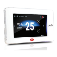
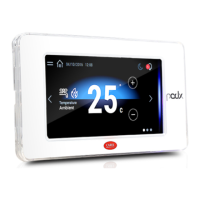
User terminal pGD Touch 7” – 7” pGD Touch 7”
+050001493 - rel. 1.0 - 20.11.2012
Introduction
The pDG Touch 7 inch graphic terminal belongs to the family of touch screen terminals
designed to make user interface with controllers in the pCO system family easy and
intuitive. The electronic technology used and the new 64K colors display allows high
quality images and advanced functionality to obtain a high aesthetic standard. The touch
screen panel also facilitates human-machine interaction making it easier to navigate
between the various screens.
Model codes
Code Description
PGDT07000FR00 BASIC Version
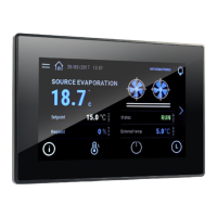
PGDT07000F120 ADVANCED Version
Contents of the package
• pGD Touch;
• power supply connectors and RS485;
• Attachment hook kit with screws;
• instruction sheet.
Warnings for installation
For state-of-the-art installation, contact qualied installers. Avoid installing the terminal in
environments with the following characteristics:
• relative humidity greater than that indicated in the technical specications;
• strong vibrations or impacts;
• exposure to aggressive and polluting atmospheres (i.e.: sulphuric and ammonia gases,
salt vapours, smoke) with subsequent corrosion and/or oxidation;
• high magnetic and/or radio interference (therefore, avoid installing machines near
transmitting antennas);
• exposure to direct sunlight and weather in general;
• wide and rapid temperature uctuations;
• areas where there are explosives or mixtures of ammable gases.
General warnings
The following requirements must be met:
• for Ethernet and RS485 communication networks, only use shielded cables;
• a power supply voltage that diers from the one required could seriously damage the
system;
• use wire terminals suitable for the terminal boards in use. Loosen each screw and insert
the wire terminal then tighten the screws. When the operation is complete, pull the
cables slightly to make sure they are properly tightened;
• do not open the product when it is under power;
• particularly low temperatures could cause a visible decrease in the response speed on
the display. This is considered normal and is not a sign of malfunction.
HMI Runtime and/or application update
Copy the update package (.ZIP le) containing the runtime or the
application or both according to the options chosen when generating
the “Update package” with 1Tool-TE to a USB drive and then connect
the drive to the pGDTouch. Hold your nger on the pGDTouch
:terminal for a few seconds until the menu is displayed
Select “Update...” to
start the Runtime
and/or application
update procedure
The update utility
will start and the
following window
:appears
Select “Auto
select best
match” and
;press next
this starts
the update
procedure. Wait for the procedure to nish
.“and press “Close
System settings
Hold your nger
on the pGDTouch
terminal for a few
seconds until the
:menu is displayed
Select “Show
system
settings”;
the main
conguration
program
.(screen will appear (following gure
The Next and Back buttons allow you to scroll through the various functions until you
highlight the one you wish in light blue. Pressing on the light blue box starts the selected
function.
Function
name
Description
Calibrate
touch
Recalibrates the touch screen. Use a stylus and carefully press the crosses following the
proposed indications.
Display
settings
Access the system menu to set the backlight auto shut o time and adjust the
brightness. Default = 5’. Auto shut o does not need to be disabled
Time Allows the adjustment of the system clock and time zone (always set at GMT)
BSP
Settings
Version: Shows the operating system version
Timers: shows the hours of operation of the system and the backlight
Buzzer: allows you to activate the buzzer sound when touching the touch screen
Network Shows the current IP data of the system
(see following g.) (address, subnet,
Gateway, DHCP, DNS) and allows access
to the ethernet port conguration
menu
Set
device
address
(new
version)
Setting the device address for protocols that
require it (Modbus RTU Server, Bacnet). The
address can only be changed for protocols
that are running. Select the communication
port (Ethernet, Com1, Com2) using the
arrow keys at the top. Make sure the
protocol is the one you want.
Use the numeric keypad to insert the address, within the minimum and maximum
values. The key removes the last number, the Clear key removes all the numbers.
The default value is assigned through 1ToolTE editor. The Cancel key cancels the
change, the OK key makes the change eective if the value entered is valid, otherwise
an error message is displayed.
Technical characteristics
Display
Type LCD TFT
Resolution 800x480 (WVGA);
Active display area 7” diagonal, 16/9
Colors 64 K
Backlighting LED
Brightness control Si
ViewingAngle (CR ≥10) Top / Bottom Left / Right = 60 / 50 deg. 60 / 60 deg.
Contrast ratio (min.) 250 (Φ=0°)
Response Time (max.) Tr =10 ms; Tf =16 ms
Color chromaticity (CIE) White (Ø = 0°) x = 0.249 ÷ 0.349; y = 0.278 ÷ 0.378
Luminance (min.) 180 cd/m2
Luminance Uniformity (min.) 70 %
System resources
Operating system Microsoft Windows CE 6.0
Microprocessor TI AM3505 – 600MHz
User memory 128 MB Flash
RAM 256 MB DDR2
User interface
Touchscreen Resistive
System LED indicators
1 green and 1 red
pGD touch 7”
7 pGD Touch
pCO Sistema
64K
PGDT07000FR00BASIC
PGDT07000F120ADVANCED
•;pGD Touch
•;RS485
•;
•
•
•
•
/
(
)
•(
)
/
•
•
•
•; RS485
•
•
•
•
(ZIP )
pGDTouch USB 1Tool-TE " "
pGDTouch
() "Update"
/ Runtime
Auto select best”
,next “match
"Close"
()
pGDTouch
Show system”
;“settings
(
)
Back Next
Calibrate
touch
Display
settings
‘Default = 5
Time
(GMT
)
BSP
Version
Timers
Buzzer
Network ) IP
(DHCP, DNS , ,) (
Set device
address
)
(
Modbus RTU Server,)
(Bacnet
(Ethernet, Com1, Com2)
Clear ,
- OK , Cancel 1ToolTE editor
-
LCD TFT
(800x480 (WVGA
9 / 16 ,
7
64 K
LED
(10≤ ) 60 / 60 50 / 60 =
/ /
(
) (0°= ) 250
( )
16= ;
10=
(
) x = 0249 ÷ 0349; y = 0278 ÷ 0378 (0° = )
(
)
/ 180
(
) 70
Microsoft Windows CE 60
() TI AM3505 – 600MHz
128 MB Flash
()
DDR2 256
"Touchscreen"
LED
1
1
(*) 1
RJ45 - 100/Auto-MDIX 10
(*) 2
RJ45 - 100/Auto-MDIX 10
USB
1 > ,
500 -
A (USB)
- 20
(**) 1
5,08
-
115 RS485
2
115 RS485
5,08
PGDT07000F120
(**) - PGDT07000F120 (*)
SELV CIRCUIT TNV
SVG 10