• Do not dispose of the product as solid municipal waste; take it to the proper collection centres
• The product contains a battery, which must be removed, separating it from the rest of the product according to the
following instructions, before proceeding with disposal
• Improper use or disposal could have a negative effect on human health and the environment
• Public or private waste collection systems defined by local legislation must be used for its disposal
• in the event of illegal disposal of waste electrical and electronic equipment, penalties have been established by the
current local laws regarding disposal
•
•
•
•
•
Use a safety transformer or power supply with separate windings that ensures equivalent insulation as established by IEC 61558-
6-2 and IEC 6155816-2-, and earth the terminal’s metal casing and G0 line (functional connection) If the pGD 7” is integrated into
a class I device where metallic parts may come into contact with dangerous voltages, a protective earth connection is required,
connecting the metal case of the terminal to the equipotential bonding of a Class I-dispositive If the same power transformer
is used for the terminal and the corresponding control device, do not reverse the G0 and G connections on the power terminals
to avoid damaging the devices
Low voltage safety/limited power source power supply
Do not open the panel casing when it is under power
Make sure the power supply is able to deliver the necessary power for proper device operation (27VA / 12W)
G0
16-2-CEI EN61558 6-2-CEI EN61558
I
pGD 7 (SELV)
( )
I
G G0
/
( 12/
27)
/ Green
/
ON
/ If flashing indicates communication state with devices
/ Red
/ On during system start up
/ If on permanently it indicates hour setting lost due to low battery
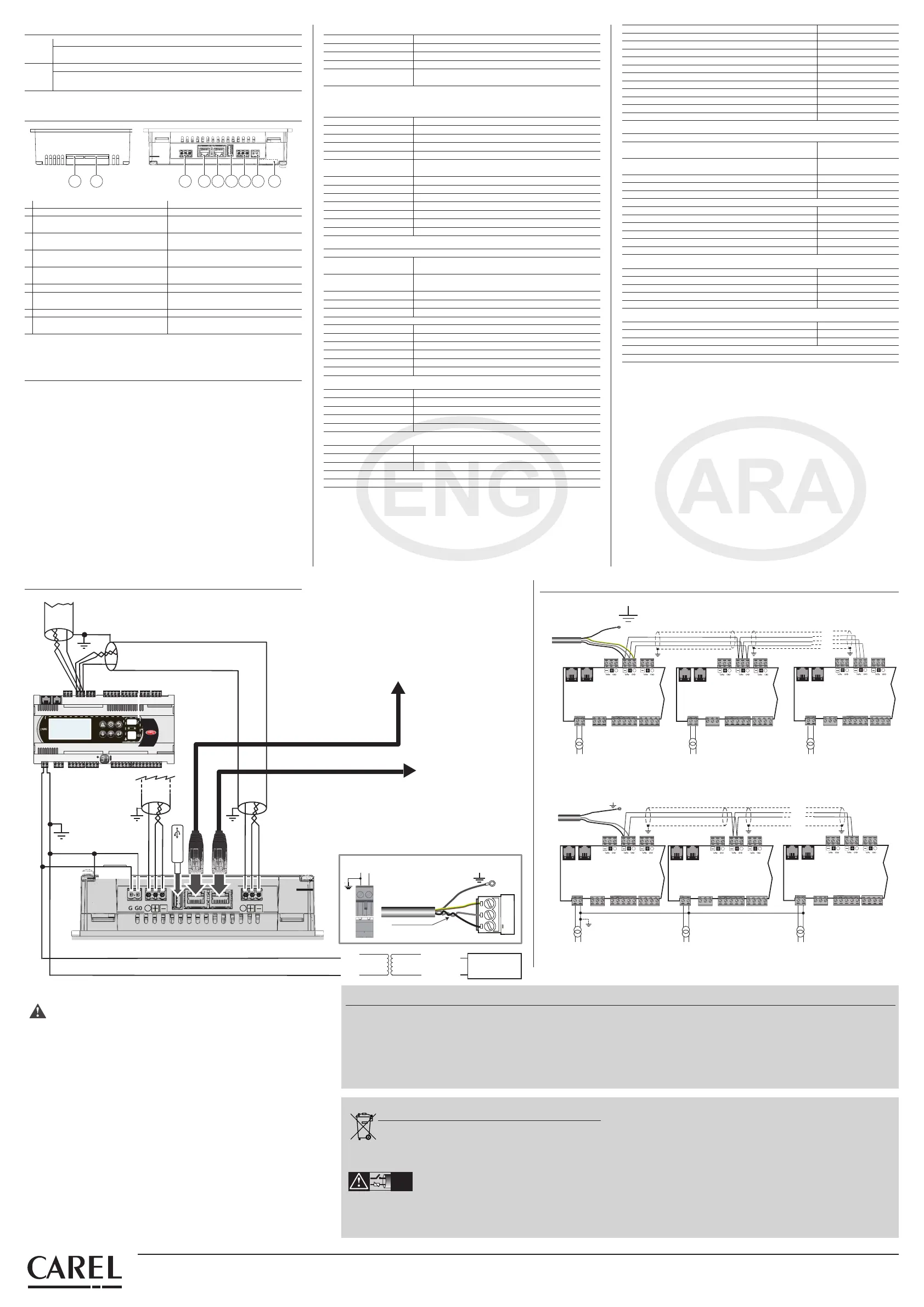
2 1 3 4 5 6 7 8 9
Fig6 / 6
Basic = PGDT07000FR00 Advanced = PGDT07000F120
1 Not present /
SD / SD card connector
2 Preset for membrane keypad /
Preset for membrane keypad /
3 RS485 port not optically-isolated /
1 584SR
RS485 port optically-isolated /
1 RS485
4 Not present /
Ethernet Port 1 (internal switch) /
1
5 Not present /
Ethernet Port 2 (internal switch) /
2
6 USB Host Port / USB Host USB Host Port / USB Host
7 RS485 port not optically-isolated /
2 RS485
RS485 port not optically-isolated /
2 RS485
8 Alimentazione / Power supply /
9 Not present /
Plug-in connector (on rear) /
(
) Plug-in
Tab 2 / 2
Note use the USB port only for Service /
USB
RS485RS485
If the RS485 port is used as Master Modbus/Carel
DO NOT connect the 120 Ohms terminal resistors into the first and the last devices of the RS485 network, this
is because the Rs485 port is HW Slave type The maximum number of devices which can be connected in the
network is 32, and the maximum lenght of it is 500 meters
Follow the diagrams using shielded cable for RS485 networks
Master Modbus/Carel
RS485
HW RS485
120
500 ,
32
,slave
RS485
To other device: max cable length 500m, max device 32
RS485 shielded twisted pair cable
To other pGD-Touch
Shielded STP CAT-5 cable
To server or network HUB
G
G0
G
G0
G
G0
OR
G
G0
Vdc
+
-
24 Vac
230 Vac
* Leggere le avvertenze per il collegamento
Read warnings for connection
GND
+
coppia intrecciata /
interfaced couple
G0/-
G/+
collegare a terra /
connect to earth
7
5
5
230 Vac
24 Vac
L
N
230 Vac
24 Vac
L
N
230 Vac
24 Vac
L
N
J26FBus2
J25 BMS2
J11 pLAN
pCO5
G
G0
J26FBus2
J25 BMS2
J11 pLAN
pCO5
G
G0
J26FBus2
J25 BMS2
J11 pLAN
pCO5
G
G0
collegare a terra /
connect to earth
Fig8 / 8
J26FBus2
J25 BMS2
J11 pLAN
pCO5
G
G0
J26FBus2
J25 BMS2
J11 pLAN
pCO5
G
G0
J26FBus2
J25 BMS2
J11 pLAN
pCO5
G
G0
collegare a terra /
connect to earth
230 Vac
24 Vac
L
N
230 Vac
24 Vac
L
N
230 Vac
24 Vac
L
N
Fig9 / 9
CAREL Industries HQs
Via dell’Industria, 11 - 35020 Brugine - Padova (Italy)
Tel. (+39) 0499716611 – Fax (+39) 0499716600 – www.carel.com – e-mail: carel@carel.com
+050001493 - rel. 1.0 - 20.11.2012
Interfaces
Ethernet Port 1 (*) Auto-MDIX 10/100 Mbit - RJ45 female
Ethernet Port 2 (*) Auto-MDIX 10/100 Mbit - RJ45 female
USB Port Host interface 2.0 - USB type A fem - 500 mA max Lmax cable < 1m
Serial Port 1 (**) RS485 max 115 Kb - Screw connections pitch 5.08
Serial Port 2
RS485 max 115 Kb not optically-isolated
Screw connections pitch 5.08
(*) only for model PGDT07000F120 - (**) optically-isolated for model PGDT07000F120
Note: the communication interfaces are not type TNV but SELV CIRCUIT type.
Functionality
Vector graphics Yes, SVG 1.0 support included
Dynamic objects Yes, Visibility, position, rotation
TrueType fonts Yes
Multi-protocol Yes
History and trends Yes. Limited to the size of the Flash memory
Multilingual
Yes, with setting of the run-time language and limited only by
the available memory
Recipes Yes. Limited to the size of the Flash memory
Alarms Yes
Event list Yes
Passwords Yes
Real Time Clock Yes, with battery back-up
Screen saver Yes
Buzzer "Beep" at touch pressure (congurable)
Ratings
Power supply
PGDT07000FR00
24Vac -15÷10% 50÷60Hz Max 1.2A (24VA)
12...30Vdc ±5% Max 0.9 Adc a 12Vdc
PGDT07000F120
24Vac -15÷10% 50÷60Hz Max 1.3A (27VA)
12...30Vdc ±5% Max 1.0 Adc a 12Vdc
Minimum power cross-section 0.5 mm
2
Max. power consumption 12W
Fuse Automatic
Weight Approx 1 kg
Battery Non rechargable lithium mod BR2330
Software class and structure A
Res. to heat and re Cat. D
Surge immunity Cat. II
Insulation class Class III, to incorporate in Class I or III devices
Environmental conditions
Working temperature -20...+60 °C
Storage temperature -20...+70 °C
Working and storage humidity 5...85 % relative, non-condensing humidity
Protection rating IP65 (front); IP20 (rear)
Pollution Grade Grade II
Dimensions
Front panel LxH 187x147 mm (7.36x5.79“)
Drilling AxB 176x136 mm (6.93x5.35“)
Depth 45+4 mm (1.77+0.16”)
Compliant with the European standards EMC and LVD Directives. UL Certicate, File E226306
CAREL INDUSTRIES reserves the right to make changes or modications to its products
without prior notice.
IMPORTANT WARNINGS
The CAREL product is a state-of-the-art product, whose operation is specified in the technical documentation supplied
with the product or can be downloaded, even prior to purchase, from the website www.carel.com - The client
(builder, developer or installer of the final equipment) assumes every responsibility and risk relating to the phase
of configuration the product in order to reach the expected results in relation to the specific final installation and/
or equipment The lack of such phase of study, which is requested/indicated in the user manual, can cause the final
product to malfunction of which CAREL can not be held responsible The final client must use the product only in
the manner described in the documentation related to the product itself The liability of CAREL in relation to its own
product is regulated by CAREL’s general contract conditions edited on the website www.carel.com and/or by specific
agreements with clients
NO POWER
& SIGNAL
CABLES
TOGETHER
READ CAREFULLY IN THE TEXT!
WARNING separate as much as possible the probe and digital input signal cables
from the cables carrying inductive loads and power cables to avoid possible electromagnetic disturbance
Never run power cables (including the electrical panel wiring) and signal cables in the same conduits
The appliance (or the product) must be disposed of separately in compliance with the local
standards in force on waste disposal
,
FLASH
(run-time)
(
) RecipesFLASH
"screen saver"
Buzzer
( ) ""
PGDT07000FR00
(
24)
12 60÷50 10÷-15 24
12
09 ±5
3012
PGDT07000F120
(
27)
13 60÷50 10÷-15
24
12
10 ±5
3012
0,5
W 12
1
BR2330
A
D
II
III I
,III
+60-20
+70-20
85 - 5
() IP20 ;() IP65
II
×
(”736x579) 187x147
AxB (”693x535) 176x136
(“016+177) 4+45
E226306 ,UL LVD EMC
CAREL INDUSTRIES
 Loading...