+05C001950 - rel. 1.3 - 02.03.2020
䇤⿈㬷⤺㡘pGDx Touch 7” -
User terminal pGDx Touch 7”
pGDx
⨀⫈ / Dimensions (mm)
183
200
231.7
10.8 42.5 230
212.5
200
2
9.7
230
28200
225.7
200
127.8
56 221.7
123.4
100
100
60
60 176
83.5
83.5
132
13010071
114.7
44.7
12.4100
124.6133.9
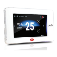
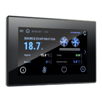
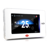
Introduction
The pGDx 7 inch graphic terminal is part of the family of touchscreen terminals designed to
simplify user interface with the pCO sistema family controllers. The electronic technology
used and the new 16.7M colour display means high quality images and advanced functions
are available for a superior appearance. The touchscreen panel moreover makes interaction
between the user and the unit much easier by simplifying navigation between the various
screens. Di erent types of installation are available, depending on the model: front or
back panel, wall surface or ush-mount. In any case, the device can be mounted either
horizontally or vertically.
Part numbers
Part number
No. RS485 ports No. ETH ports WiFi connectivity
PGR07****B***
1- -
PGR07****W***
1-
PGR07****D***
2- -
PGR07****C***
11 -
PGR07****R***
11
PGR07****F***
22 -
PGR07****G***
22
PGB07****E***
-1 -
PGB07****M***
-2 -
PGB07****I***
-2
Packaging contents
pGDx; power supply and RS485 connectors; installation kit; technical lea et, WiFi antenna
(only for models where tted, PG*07***D[G,I,R,W]***). Not included: frame, PGTA00TRX0
power supply and wall mounting boxes
.
Installation warnings
For correct installation contact a quali ed installer.
Do not install the terminals in environments with the following characteristics:
• relative humidity greater than the value speci ed in the technical speci cations;
• strong vibrations or knocks;
• exposure to aggressive and polluting atmospheres (e.g.: sulphur and ammonia fumes,
salt spray, smoke) so as to avoid corrosion and/or oxidation;
• strong magnetic and/or radio frequency interference (therefore avoid installing the units
near transmitting antennae);
• exposure to direct sunlight or the elements in general;
• large and rapid uctuations in the room temperature;
• environments where explosives or mixes of ammable gases are present.
The following requirements must be met
• with built-in temperature/humidity sensor, it is recommended to:
– only use frame tted ventilation openings
– install the terminal away from air streams coming from heating/cooling systems
– if installed vertically, position the probe at the bottom of the display
• only use shielded cables for Ethernet and RS485 communication networks;
• power supply voltages other than those speci ed may seriously damage the system;
• use cable ends suitable for the corresponding terminals. Loosen each screw and insert
the cable ends, then tighten the screws. When the operation is completed, slightly tug
the cables to check they are su ciently tight;
• in models with an external WiFi antenna, ensure at least basic insulation (500 Vac
according to IEC 60730-1) between the RP-SMA connector and the protective earth;
• do not open the product when powered;
• operation at low temperatures may cause a noticeable decline in the response speed
of the display. This should be considered normal and does not indicate a malfunction.
• for correct installation, apply a tightening torque of 0.4 Nm. Furthermore, on
PG*07***[N,T]**** models, to ensure the declared IP value, the panel roughness index
must not exceed 1.6 µm and the gasket must be tted correctly;
• avoid any contact of the product with live parts.
• be sure that cables are accurately xed in order to avoid contact with live parts in case of
their accidentally disconnection.
Meaning of the colours on the notifi cation bar
At power-on, the noti cation bar brie y shows a blue signal to indicate the start of the
boot phase. The subsequent signals are then managed by the application program
developed using c.touch.
HMI Runtime and/or application update
1. Copy the update package (.ZIP le) containing the runtime
or application, or both, depending on the options selected
when generating the “Update package” using c.touch, to a
USB pendrive and then plug the pendrive into the pGDx and
hold the pGDx terminal screen for a few seconds until the
shortcut menu is displayed, disableable application side (see
the gure on the side):
2. Select “Update…” to
start the Runtime and/
or application update
procedure. The update
utility will start and the
following window will
be displayed:
3. Then follow the
guided procedure,
selecting the le
saved on the USB
pen drive and
clicking the next
button to con rm.
System settings
Touch and hold the pGDx terminal screen
for a few seconds until the shortcut
menu is displayed (see the gure below).
Select “Show system settings”; the main
con guration program screen will be
displayed ( gure on the side):
Below is a list of the functions relating to the di erent menu items:
Language Set the system language (not the c.touch application)
System
Contains information on the pGDx: BSP version, Memory, Timers
and temperature / humidity sensor (if featured)
Logs Download the system log les
Date & Time Set pGDx date and time using the automatic or manual procedure
Network
Show current system IP data (address, subnet, Gateway, DHCP, DNS)
and access the Ethernet and WiFi interface
Services
Start/stop various system services (Modbus server port, pGDx
network address,…)
Management
Update the di erent pGDx BSP partitions (Con gOS, MainOS,
Bootloader, Splash image, etc.…)
Display
Set brightness, backlight timeout, screen orientation and touch
panel calibration
Restart Restart the system
Authentication Set the password used to access
EXIT Exit the menu
㣞㘇➓䓑㞅ミ (㧈㵝1c) - ⥛㠘⫛㕌PGTA00SM70
Accessory for wall surface installation (ref. Figure 1c) - P/N: PGTA00SM70
㣗㧌㬞➓䓑㞅ミ (㧈㵝1d) - ⥛㠘⫛㕌 PGTA00RM70
Accessory for ush-mounted wall installation (ref. Figure 1d) - P/N: PGTA00RM70
䎞㘇 / Frontal
200
188
213
115.5
100
88
M3 self-blocking inserts
or Ø 4.2 for screw
+ counter-screw
Fig.1a
(*) IP66: 带垫圈且薄片厚度在1.2 - 6 mm之间 / with gasket and sheet thickness from 1.2 - 6 mm
IP20: 无垫圈且薄片厚度在0.8 - 6 mm之间 / without gasket and sheet thickness from 0.8 - 6 mm
背面 / Back
M3 threaded pins
184
200
10.4
5.4
125.6
100
R4
policarbonate
Fig.1b
(*) IP20: 薄片厚度在0.8 - 2 mm之间 / sheet thickness from 0.8 - 2 mm
墙面安装 Wall surface
Fig.1c
墙面安装/ Wall mounting
ⶪ㡗㣞 Dry wall
220
122
Fig.1d
⢃㠞㼀㎣⪊⺞
(㆗㬫䇤䇻⤪䇤㶃
䐤ポ㝭)
Flat cable passage
(only in case
of external keypad)
㶃㌓⥛㠘⫛㕌/Frame code: PGTA**F[T,H][2,3]*
非Carel供货 / Not supplied by Carel
⡙䓃
㤌㹑ㅌ⮈䊕㼀
⪊⺞㣗㧌㬞➓
䓑⼱
Note:
Do not run power
cables inside the
ush-mount box
⡙䓃
㤌㹑ㅌ⮈䊕㼀
⪊⺞㣗㧌㬞➓
䓑⼱
Important:
keep the at cable
isolated from the
metal panel
➖㼀㼅 / Wall box
standard ITA/CHN/DEU/USA
䅃⫔㏜䐱⺛⭣⺛㗡⺛
⢋䓝
㶃㌓⥛㠘⫛㕌
Frame code:
PGTA**F[B,W][2,3]*
(*)
䔊䓑⼮➓䓑 /
Assembly and installation (mm)
㶃㌓⥛㠘⫛㕌/Frame code: PGTA**F[T,H][2,3]*
⡙䓃
㤌㹑ㅌ⮈䊕㼀
⪊⺞㣗㧌㬞➓
䓑⼱
Note:
Do not run power
cables inside the
ush-mount box
⥛㠘ㆊ㩽
pGDx 7⫈㵝㾯䐶Ⱜ㬨⪆㘟㬞㻵㬟㠢⥛㠘㻖㑱䐱⭥䄜⤠䓉㸋ビ⿐䈌pCO sistema㻖
㑱㋹䐧㡘⭥ⰵㅴⱙ㪉ェ᱄⪬㵝㾯䐶Ⱜ⤪䇤⭥⮈䓴ゝ㭖ゑ㾣㾮⭥16.7百万㩌⤫㻵㬟
㋪㳂⹊ⷀ㠘䐫㵝㼒⼮㻩㆙⭥⹇㚽㵝㾯ㆈ㘇ⷝゴ⨗䐻᱄⪆㘟㬞㘇⟆ビ⿐㑬⤜㵍ㆈ㘇
䐏ヅ⭥⭝⼞㬚䇤⿈⼮〛䔊䐏ヅ⭥⿆Ⱀⷝゴビ⭆᱄䇱ⱁ䐷➓䓑㏁㾮⭥⤜㵍⥛㠘㋪㳂
⹊䎞㘇〓⡔⟆᱃㣞㘇➓䓑〓㣗㧌㬞➓䓑᱄⭌⤜⤪䇤㚥䐷㾮⼦⪬䐶Ⱜ㉚㋪䄵㯏
㠞➓䓑〓⪚䐒➓䓑᱄
⥛㠘⫛㕌
⫛㕌
RS485Ⱜ㋻㭞㑠 ETHⰬ㋻㭞㑠 WiFi 连接
PGR07****B***
1- -
PGR07****W***
1-
PGR07****D***
2- -
PGR07****C***
11 -
PGR07****R***
11
PGR07****F***
22 -
PGR07****G***
22
PGB07****E***
-1 -
PGB07****M***
-2 -
PGB07****I***
-2
⟝䓑㘘㻙
pGDx䐶Ⱜ⮈䊕⼮RS485㑍ㅴ㵘㆗㬫䇤⫙⪬ㅴ㵘⭥㾮⼦➓䓑䔊ミゝ㭖㸥
⭖Wi-Fi㳍㼀㆗㬫䇤⫙⪬ㅴ㵘⭥㾮⼦PG*07***D[G,I,R,W]***᱄⤜⟝㎉㯽㑰㶃
㌓PGTA00TRX0⮈䊕⼮➖㼀⼱᱄
➓䓑䓃䅃㬣㼏
㸋㦘⡄➓䓑䎞㦘㤌㑋㕈䇱䓫䐫⭥➓䓑⹅᱄
㤌㹑ㅌ䐶Ⱜ➓䓑䊻㉀䇱㻣㑱㲹⮄⭥㈔䐱
㼁ⰵ㬋Ⱙⷀ䇻ゝ㭖⺇ⷒ䐱⺇Ⰹ⭥䐖
㉀䇱㣠㑳䎑Ⱀ〓⨆〘
⡊㔗䇻㣷㬕⼮㸼㦟䐱⭥㈔㏞㧈㒓⼮➒⭥㡙㳆᱃䁯㹎᱃䁭㹎䄵ⳡ䐚ⶐ㬕
⼮〓䂖⿐
⫇䊻㣠㑳⪦㾵⼮〓㸿㼀⮈㠖㔫ⶪ㦦⭥㈔䅓⪬㣱㹑➓䓑䊻ⳃ㪅㳍㼀㆝
⡊㔗䊻䂕⺃䐒㪅⭥㈔䐱᱄
Ⳡヅ㸣Ⱙ⤉Ⱀ⫔㣳を㯺
⫇䊻⡍䍉㹐〓㋪㦝㡙㳆」⼰㹐᱄
䄵㻣䄋㤔⡹㿌㕛䔄
㧈⺜㚻䐤㸣Ⱙ㬋Ⱙ⪌ⶱ㡘ㅉ䅊
– 䐜㬚䇤㞅䐤㵉ⴈ㋻⭥㘇⟆
– ㅌ㻵㬟㠢➓䓑䊻䊗㏌䐧㏅䐧㦩㻖㵔㡙㒘㶃
– 㧈⺜㬨⪚䐒➓䓑㤌ㅌ⪌ⶱ㡘Ⰹ㸜䊻㻵㬟㠢㻣Ⳟ
㆗㬚䇤㠢⡯㼀䇤䇻Ethernet⼮RS485㵉䁗㶙㕈
㧈㬚䇤⢋Ⰹ䄵㶃⭥⮈䁚㋪㚽。䁰䐹㰑㻖㵔
㬚䇤㬫⼰䇻㼁䇇䐶Ⱜ⭥㼀㎣㵘᱄㯪㋋㗠㔾㯠⤃⥆㧌㼀㎣㵘㦜⽔㆕㔾㯠᱄⤺
䔘㶋⧪⽔㤂㤂㎎Ⱀ㼀㎣ネ⥊㼀㎣㬨ⴒ䄲Ⰹ⼤
㧈⪆㘟㠢㬚䇤㶃䐤WiFi㳍㼀㦘⡄䐢㩺〚⡟⭥ⷕ㏌ (500 Vacⷚ㈾IEC 60730-1) 䊻
RP-SMAㅴ㵘⼮⡄⿅ㅴ⭹䐏ヅ
㤌㹑䊻㩰⮈㬒⫓㋋⡟䐶Ⱜ
⭮㸣䊬㾱㋪㚽⭝䐣㻵㬟㠢ⳕ䇇㯺Ⱙ⭥㻵䑙㻣ㅖ᱄⪬䐷㻷㼔⡜㬴㸋䎞⧄㻷㼔ⱙ⤜
。⢋㬗㸋䍰
䎞㦘➓䓑Ⳟ㬞㸋㔾㯠㆕㝅㑇㸋04 Nm⪬㶃ⰵ䇻㾮⼦PG*07***[N,T]****,要
确保标称的IP防护等级,面板粗糙度指数不能超过1.6µm,且垫圈必须配置合
适;
⡽㘃ㅴ⪆䐶Ⱜ㩰㦯⼯⫙⮈⭥⤠ミ
㦘⡄㼀㎣Ⰹ䓝㦘⡽㘃ㅴ⪆⫙⮈⤠ミ䄵ⳡ䐶Ⱜⳃ㪛䅃㶃ⰰ㋋᱄
㵉䐋㎙㩰⭥䁶㩌⼍䅆
㩰⮈㬒㵉䐋㎙Ⱝ㬒㻵㬟䄜㎗㩌㾦⼦⢎㬟bootㅸⰯ㡕Ⱀ᱄㰇⽔⭥㾦⼦ㅌ䇪
c.touch㋋ⳃ⭥䇇䇤⧭㿓㆙㾱㏎᱄
HMI䊬㾱㬒ヅ⼮〓⧭㿓ⷝ㾣
ⷚ㈾䇤c.touch㪛⧪“Update package” )ⷝ㾣⟝㬒䁂䋒⭥
䁂㼏ㅌ⟝⼍䊬㾱㬒ヅ〓⧭㿓〓㑞Ⱍ䇱⭥⭥ⷝ㾣⟝
(.ZIP le)ⶕ䐧⭞䄜USB㤞Ⱀ㡘㦜⽔䊺ㅌUSB㤞Ⱀ㡘
⥆⭞pGDx➕䓂pGDx䐶Ⱜ㻵㬟㠢⧷㿙゙㘌䐴䐒⭞㻵
㬟㌍ㅾ⤬⭆㋪㬚⧭㿓⥁㬈㾈⤯㋝䇳⥁㵝
䁂䋒“Update…”)ⷝ㾣
䊬㾱㬒ヅ⼮〓⧭㿓
ⷝ㾣᱄㡕Ⱀⷝ㾣㦜
⽔ㅌ㻵㬟㻣㘇䎃
⪑㋻
㦜⽔➕䍶䅞⭝⭥
⤞䑉䁂䋒⡄⫇
䊻USB㤞Ⱀ㡘㩰
⭥㸥ミ⤃㣳⮄
〘㻣䄜➕㝆䄵
㦘㦰᱄
㻖㵔㪉Ⰹ
⪆Ⱀ⤃➕䓂pGDx䐶Ⱜㆈ㘇⧷㿙゙㘌
䐴䐒⭞㻵㬟㌍ㅾ⤬⭆㧈㻣㵝
䁂䋒㻵㬟㻖㵔㪉Ⰹ“Show system
settings”䑘䄋㞅䐤⧭㿓ㆈ㘇ㅌ㻵㬟
㧈⥁㘇㵝
㻣⢎㸋䈌⤜㵍⤬⭆㼏㚠䇱⭥⹇㚽㤆⭆
䈐䁵
㪉Ⰹ㻖㵔䈐䁵⳨c.touch⧭㿓
㻖㵔
⟝⼍䊻pGDx㩰⭥㾦㻃BSP⟇⡟⫇⪃㡘Ⰹ㬒㡘⼮㸣Ⱙ㬋
Ⱙ⪌ⶱ㡘㧈⺜䄲㞅䐤
㦶䐟 㻣䊹㻖㵔㦶䐟㸥ミ
㦶㠻㬒ヅ
㬚䇤䓵Ⱀ〓㬷Ⱀ⤞䑉㪉ⰉpGDx⭥㦶㠻⼮㬒ヅ
㶙㕈
㻵㬟⭒㣑㻖㵔IP㭞㈾(⭹䐘᱃䓴㶙㕈᱃㶙᱃DHCP᱃DNS)⤃ⳤ
㸫䄵㲌㶙⼮WiFiㆈ㘇
ⴟ㹒
㡕Ⱀ㵄䐚⤜㵍㻖㵔㪉⡙Modbusⴟ㹒㡘Ⱜ㋻pGDx㶙㕈⭹
䐘…
㏎
ⷝ㾣⤜㵍pGDx BSP㤙(Con gOS, MainOS, Bootloader㋋〛㵝
㼒⭩⭩…)
㻵㬟 㪉Ⰹ㑢Ⱙ⡔⺃⧍㬒ㆈ㘇Ⳟ㼓⼮⪆㋹㘇⟆㾄䓝
䐹㡕 䐹㡕㻖㵔
㬻㦉 㪉Ⰹ㗽㕌䇤䇻ⳤ㸫
㵬⨗ 㵬⨗⤬⭆
⥛㠘⪇䐤
⡟䓑䐤〓⥛㠘⡹㿌䄡䍶⭒⭹䇻⳰㡛㹐⪇㏎⭥䇱㾈ⳉ⺇⭆Ⱑ㆙㾱
⪇㏎᱄
/
Disposal of the product: The appliance (or the product) must be disposed of separately in
compliance with the local standards in force on waste disposal.