Signifi cato LED del pannello anteriore
Front panel LED meaning
Verde
Green
Presenza alimentazione / Power supply ON
Se lampeggiante indica stato comunicazione in corso con i dispositivi
If fl ashing indicates communication state with devices
Rosso
Red
Acceso durante l’avvio del sistema / On during system start up.
Se acceso in modo permanente indica perdita settaggio ora causa batteria
esaurita / If on permanently it indicates hour setting lost due to low battery
Descrizione morsetti / Terminals description
2 1 3 4 5 6 7 8 9
Fig.6
Basic = PGDT07000FR00 Advanced = PGDT07000F120
1 Non presente /
Not present
Connettore SD card /
SD card connector
2 Predisposizione per tastiera a membrana
Preset for membrane keypad
Predisposizione per tastiera a membrana
Preset for membrane keypad
3 Porta RS485 n. 1 non optoisolata
RS485 port not optically-isolated
Porta RS485 n. 1 optoisolata
RS485 port optically-isolated
4 Non presente /
Not present
Porta Ethernet 1 /
Ethernet Port 1
(internal switch)
5 Non presente /
Not present
Porta Ethernet 2 /
Ethernet Port 2
(internal switch)
6 Porta USB Host /
USB Host Port
Porta USB Host /
USB Host Port
7 Porta RS485 n. 2 non optoisolata
RS485 port not optically-isolated
Porta RS485 n. 2 non optoisolata
RS485 port not optically-isolated
8 Alimentazione /
Alimentazione
Alimentazione /
Power supply
9 Non presente /
Not present
Connettore Plug-in (sul retro) /
Plug-in connector (on rear)
Tab. 2
Nota / Note: utilizzare la porta USB solo per service / use the USB port only for Service
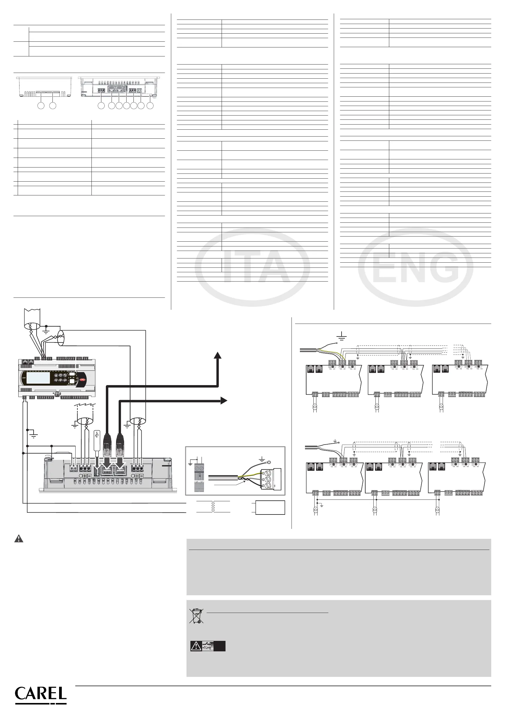
Rete RS485 / Rete RS485
Se la porta RS485 è usata come Master Modbus/Carel:
NON collegare le resistenze di terminazione da 120 ohm sul primo e sull’ultimo
dispositivo della rete in quanto la porta RS485 è di tipo HW slave, il numero massimo
di dispositivi collegabili nella rete è 32 e la lunghezza massima della rete è 500 m.
If the RS485 port is used as Master Modbus/Carel:
DO NOT connect the 120 Ohms terminal resistors into the fi rst and the last devices
of the RS485 network, this is because the Rs485 port is HW Slave type. The maximum
number of devices which can be connected in the network is 32, and the maximum
lenght of it is 500 meters.
Seguire gli schemi indicati utilizzando cavo schermato per reti RS485
Follow the diagrams using shielded cable for RS485 networks
Collegamenti elettrici / Electrical connections
To other device: max cable length 500m, max device 32
RS485 shielded twisted pair cable
To other pGD-Touch
Shielded STP CAT-5 cable
To server or network HUB
G
G0
G
G0
G
G0
OR
G
G0
Vdc
+
-
24 Vac
230 Vac
* Leggere le avvertenze per il collegamento
Read warnings for connection
GND
+
coppia intrecciata /
interfaced couple
G0/-
G/+
collegare a terra /
connect to earth
Fig. 7
CAREL Industries HQs
Via dell’Industria, 11 - 35020 Brugine - Padova (Italy)
Tel. (+39) 0499716611 – Fax (+39) 0499716600 – www.carel.com – e-mail: carel@carel.com
+050001490 - rel. 1.0 - 20.11.2012
Interfacce
Porta Ethernet 1 (*) Auto-MDIX 10/100 Mbit - RJ45 femmina
Porta Ethernet 2 (*) Auto-MDIX 10/100 Mbit - RJ45 femmina
Porta USB Host interface 2.0 - USB tipo A fem - 500 mA max Lmax cavo < 1m
Porta Seriale 1 (**) RS485 max 115 Kb - Conn. sconnettibile a vite passo 5,08
Porta Seriale 2
RS485 max 115 Kb non optoisolata
Conn. sconnettibile a vite passo 5,08
(*) solo per modello PGDT07000F120 - (**) optoisolata per modello PGDT07000F120
Nota: le interfacce di comunicazione non sono di tipo TNV ma di tipo SELV CIRCUIT.
Funzionalità
Grafi ca vettoriale Si, incluso supporto SVG 1.0
Oggetti dinamici Si Visibilità, posizione, rotazione
TrueType fonts Si
Multiprotocollo Si
Storico e trend Si. Limitato alla memoria della Flash memory
Multi-lingue
Si, con impostazione della lingua run-time e limitato solo dalla
memoria disponibile
Recipes (ricette) Si. Limitato alla memoria della Flash memory
Allarmi Si
Lista event Si
Passwords Si
Real Time Clock Si, con batteria di back-up
Screen saver Si
Buzzer “Beep” alla pressione del touch (confi gurabile)
Ratings
Alimentazione
PGDT07000FR00
24 Vac -15÷10% 50÷60 Hz Max 1.2 A (24 VA)
12...30 Vdc ±5% Max 0.9 Adc a 12 Vdc
PGDT07000F120
24 Vac -15÷10% 50÷60 Hz Max 1.3 A (27 VA)
12...30 Vdc ±5% Max 1.0 Adc a 12 Vdc
Sezione minima cavi
alimentazione
0,5 mm
2
Potenza massima assorbita 12 W
Fusibile Automatico
Peso Approx 1 kg
Batteria Non ricaricabile al litio mod BR2330
Classe e struttura
del software
A
Res. al calore e al fuoco Cat. D
Imm. contro le sovratens. Cat. II
Classe isolamento Classe III, da incorporare in dispositivi di classe I o III
Condizioni ambientali
Temperatura di lavoro -20...+60 °C
Temperatura di immagaz. -20...+70 °C
Umidità di lavoro e
immagazzinamento
5...85 % umidità relativa, non-condensante
Grado di protezione IP65 (frontale); IP20 (retro)
Grado di inquinamento Grado II
Dimensioni
Pannello frontale LxH 187x147 mm (7.36x5.79“)
Foratura AxB 176x136 mm (6.93x5.35“)
Profondità 45+4 mm (1.77+0.16”)
Conforme alle direttive europee EMC e LVD. Certifi cato UL, File E226306
CAREL INDUSTRIES si riserva la possibilità di apportare modifi che o cambiamenti ai propri
prodotti senza alcun preavviso.
Interfaces
Ethernet Port 1 (*) Auto-MDIX 10/100 Mbit - RJ45 female
Ethernet Port 2 (*) Auto-MDIX 10/100 Mbit - RJ45 female
USB Port Host interface 2.0 - USB type A fem - 500 mA max Lmax cable < 1m
Serial Port 1 (**) RS485 max 115 Kb - Screw connections pitch 5.08
Serial Port 2
RS485 max 115 Kb not optically-isolated
Screw connections pitch 5.08
(*) only for model PGDT07000F120 - (**) optically-isolated for model PGDT07000F120
Note: the communication interfaces are not type TNV but SELV CIRCUIT type.
Functionality
Vector graphics Yes, SVG 1.0 support included
Dynamic objects Yes, Visibility, position, rotation
TrueType fonts Yes
Multi-protocol Yes
History and trends Yes. Limited to the size of the Flash memory
Multilingual
Yes, with setting of the run-time language and limited only by
the available memory
Recipes Yes. Limited to the size of the Flash memory
Alarms Yes
Event list Yes
Passwords Yes
Real Time Clock Yes, with battery back-up
Screen saver Yes
Buzzer "Beep" at touch pressure (confi gurable)
Ratings
Power supply
PGDT07000FR00
24Vac -15÷10% 50÷60Hz Max 1.2A (24VA)
12...30Vdc ±5% Max 0.9 Adc a 12Vdc
PGDT07000F120
24Vac -15÷10% 50÷60Hz Max 1.3A (27VA)
12...30Vdc ±5% Max 1.0 Adc a 12Vdc
Minimum power cross-section 0.5 mm
2
Max. power consumption 12W
Fuse Automatic
Weight Approx 1 kg
Battery Non rechargable lithium mod BR2330
Software class and structure A
Res. to heat and fi re Cat. D
Surge immunity Cat. II
Insulation class Class III, to incorporate in Class I or III devices
Environmental conditions
Working temperature -20...+60 °C
Storage temperature -20...+70 °C
Working and storage humidity 5...85 % relative, non-condensing humidity
Protection rating IP65 (front); IP20 (rear)
Pollution Grade Grade II
Dimensions
Front panel LxH 187x147 mm (7.36x5.79“)
Drilling AxB 176x136 mm (6.93x5.35“)
Depth 45+4 mm (1.77+0.16”)
Compliant with the European standards EMC and LVD Directives. UL Certifi cate, File E226306
CAREL INDUSTRIES reserves the right to make changes or modifi cations to its products
without prior notice.
Schema per collegamento a pCO
5
/
Connection to pCO
5
230 Vac
24 Vac
L
N
230 Vac
24 Vac
L
N
230 Vac
24 Vac
L
N
J26FBus2
J25 BMS2
J11 pLAN
pCO5
G
G0
J26FBus2
J25 BMS2
J11 pLAN
pCO5
G
G0
J26FBus2
J25 BMS2
J11 pLAN
pCO5
G
G0
collegare a terra /
connect to earth
Fig. 8
J26FBus2
J25 BMS2
J11 pLAN
pCO5
G
G0
J26FBus2
J25 BMS2
J11 pLAN
pCO5
G
G0
J26FBus2
J25 BMS2
J11 pLAN
pCO5
G
G0
collegare a terra /
connect to earth
230 Vac
24 Vac
L
N
230 Vac
24 Vac
L
N
230 Vac
24 Vac
L
N
Fig. 9
Utilizzare un trasformatore di sicurezza d’isolamento conforme alle norme CEI EN61558-2-6 e CEI
EN61558-2-16 e collegare la carcassa metallica del terminale e la linea G0 a terra (collegamento
funzionale). Per l’alimentazione continua utilizzare un alimentatore che garantisca una tensione
di sicurezza (SELV). Nel caso il pGD 7” venga incorporato in un dispositivo classe I in cui sussiste la
possibilità che le parti metalliche possano entrare in contatto con tensioni pericolose è necessario
eff ettuare un collegamento a terra di protezione, collegando la carcassa metallica del terminale al
nodo equipotenziale del dispositivo di classe I. In caso di unico trasformatore di alimentazione tra
il terminale e il relativo dispositivo di controllo, si raccomanda di non invertire le connessioni G0 e
G sui morsetti di alimentazione per evitare danni ai dispositivi.
Alimentatore a bassissima tensione di sicurezza/sorgente di potenza limitata.
Non aprire l’involucro dei pannelli quando sono alimentati
Verifi care che l’alimentatore sia in grado di erogare la potenza necessaria per il corretto
funzionamento dell’apparecchiatura (27 VA/12 W).
Use a safety transformer or power supply with separate windings that ensures equivalent
insulation as established by IEC 61558-2-6 and IEC 61558-2-16, and earth the terminal’s metal
casing and G0 line (functional connection). If the pGD 7” is integrated into a class I device where
metallic parts may come into contact with dangerous voltages, a protective earth connection
is required
, connecting the metal case of the terminal to the equipotential bonding of a Class
I-dispositive.
If the same power transformer is used for the terminal and the corresponding
control device, do not reverse the G0 and G connections on the power terminals to avoid
damaging the devices.
Low voltage safety/limited power source power supply
Do not open the panel casing when it is under power
Make sure the power supply is able to deliver the necessary power for proper device operation
(27VA / 12W).
IMPORTANT WARNINGS
The CAREL product is a state-of-the-art product, whose operation is specifi ed in the
technical documentation supplied with the product or can be downloaded, even prior
to purchase, from the website www.carel.com. - The client (builder, developer or installer
of the fi nal equipment) assumes every responsibility and risk relating to the phase of
confi guration the product in order to reach the expected results in relation to the specifi c
fi nal installation and/or equipment. The lack of such phase of study, which is requested/
indicated in the user manual, can cause the fi nal product to malfunction of which CAREL
can not be held responsible. The fi nal client must use the product only in the manner
described in the documentation related to the product itself. The liability of CAREL in
relation to its own product is regulated by CAREL’s general contract conditions edited on
the website www.carel.com and/or by specifi c agreements with clients.
NO POWER
& SIGNAL
CABLES
TOGETHER
READ CAREFULLY IN THE TEXT!
WARNING: separate as much as possible the probe and
digital input signal cables from the cables carrying inductive loads and power
cables to avoid possible electromagnetic disturbance. Never run power cables
(including the electrical panel wiring) and signal cables in the same conduits.
Disposal of the product
The appliance (or the product) must be disposed of separately in
compliance with the local standards in force on waste disposal.
Regole per lo smaltimento / Disposal regulations
• Non smaltire il prodotto come rifi uto solido urbano ma smaltirlo negli appositi centri di raccolta.
• Il prodotto contiene una batteria ed è quindi necessario rimuoverla separandola dal resto del
prodotto seguendo le istruzioni riportate di seguito prima di procedere al suo smaltimento.
• Un uso improprio o uno smaltimento non corretto potrebbe avere eff etti negativi sulla salute
umana e sull’ambiente.
• Per lo smaltimento vanno utilizzati i sistemi di raccolta pubblici o privati previsti dalle leggi locali.
• In caso di smaltimento abusivo dei rifi uti elettrici ed elettronici sono previste sanzioni stabilite
dalle vigenti normative locali in materia di smaltimento.
•
Do not dispose of the product as solid municipal waste; take it to the proper collection centres.
•
The product contains a battery, which must be removed, separating it from the rest of the
product according to the following instructions, before proceeding with disposal.
•
Improper use or disposal could have a negative eff ect on human health and the environment.
•
Public or private waste collection systems defi ned by local legislation must be used for its
disposal.
•
in the event of illegal disposal of waste electrical and electronic equipment, penalties have been
established by the current local laws regarding disposal.
 Loading...