CAREL Industries HQs
Via dell’Industria, 11 - 35020 Brugine - Padova (Italy)
Tel. (+39) 0499716611 – Fax (+39) 0499716600 – www.carel.com – e-mail: carel@carel.com
+05C001895 - rel. 1.2 - 02.04.2019
CAREL⡄㒕⤜䊅㻩䐋ⱙ㾿ⶥ⥛㠘⭥㦉㑇᱄
CAREL INDUSTRIES reserves the right to modify the features of its products without prior notice.
Technical specifications
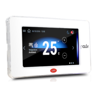
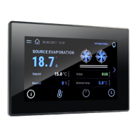
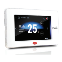
Display
Type LCD TFT
Resolution 480x272 Wide
Active display area 4.3” diagonal
Colours 65 K
Backlighting LCD - Lifetime 20 khrs @ 25 °C
Brightness control Yes - auto-o by default after 15 min
Visual angle (CR ≥10) Up/Down (40/50 deg.) - Left/Right (50/50 deg.)
Contrast (typical) 350 (Φ=0°)
Brightness (typical) 200 cd/m
2
User interface
Touchscreen Resistive
System signal LEDs 8-colour notication bar
Interfaces
Ethernet port Auto-MDIX 10/100 Mbit - RJ45 female
STP CAT 5 cable Lmax = 100 m
Wi Fi IEEE 802.11 b/g/n - STATION/ACCESS POINT mode
Built-in/external antenna based on model
Max Transmit Power = 17dBm
External antenna remote mounting Lmax = 2 m
External antenna connector RP-SMA female
(for models PG*04***D[H,R,W]***)
USB port () Host interface 2.0 - micro USB -B - 150 mA max
(do not use to charge devices) - Lmax = 1m
Serial port with RJ12 connector RS485 max 115.2 Kb/s
6-wire telephone cable Lmax = 2m
Serial port with screw terminal () RS485 max 115,2 Kb/s
Removable screw connector 3,81mm pitch
Shielded twisted pair cable AWG 20-22 for ±
Lmax = 500m - tightening torque 0.25Nm (2.2lbf x in)
Temperature / humidity probe 0 to 50 °C / 20 to 80% rH
0 to 50 °C ±1 °C (static air)
20 to 80% ±5% (static air)
()
only for service. The USB port can be damaged by ESD (Electro-Static Discharges).
It’s recommended to adopt appropriate precautions in order to avoid failures.
() opto-isolated for model PGR04****[C,R]***
Functions
Vector graphics Yes, includes SVG 1.0 support
Dynamic objects Yes Visibility, position, rotation
TrueType fonts Yes
Multi-protocol Yes
Logs and trends Yes. Limited to Flash memory capacity
Multilanguage Yes, run-time language setting and limited only by
available memory
Recipes Yes. Limited to Flash memory capacity
Alarms Yes
Event list Yes
Passwords Yes
Real Time Clock () Yes, with backup battery
Screen saver Yes
Buzzer () “Beep” when pressing the touchscreen (settable)
() only on models where featured
Electrical
PGR04****A*** power supply Power supply from pCO via RJ12 telephone connector
(check that the power supplied by the controller is
compatible with PGDx power consumption)
PG*04****[B,C,E,H,R,W]***power
supply
24Vdc supplied by PGTA00TRX0 accessory
Lmax = 50 m(--)- cable cross section AWG 12-20
tightening torque 0.8 Nm (7 lbf x in)
Max Power Absorption 7W, exception PGR04****A*** = 3W
Fuse Automatic
Weight Approx. 250 g
Battery Non-rechargeable lithium model BR1225
Software class and structure A
Purpose of control operation control
Controller construction independently mounted control (PG*04***[F,T]****)
incorporated control (PG*04***[R,D,W]****)
Type of automatic action type 1 action
Heat and re resistance Cat. D
Overvoltage category Cat. III
Insulation class Class III
() For models PGR04***[F,T ]****. To connect -Vdc to earth follow the instructions on the
connection diagrams
() For models– for ush mounting the PGTA00TRX0 accessory must be installed in a
dedicated box
() Power supply range: 24 Vdc ± 10%
Environmental conditions
Operating temperature PG*04***[T,D]****: -20T60 °C
PG*04***[F,R,W]****: 0T50 °C
Storage temperature PG*04*******: -30T70 °C
Maximum operating and storage
relative humidity
85% @ 40 °C non-condensing
Ingress protection PG*04***T****: IP65, NEMA Type 1 (front)
if coupled with PGTA**F [B,W][0,1]* (frame)
PG*04***[D,F,R,W ]****: IP20, NEMA Type 1 (front)
Pollution degree 3
㶙㕈㑍ㅴ /
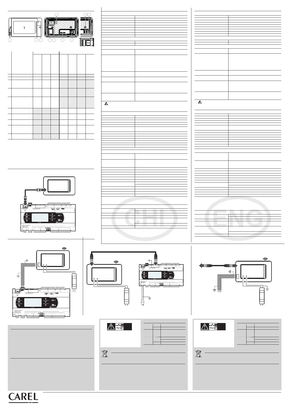
Network connection:
4 10 6 3 92 1
75
GND
RX/TX +
+
–
+
–
RX/TX –
GND
RX/TX +
RX/TX –
8
Fig.4
Mounting/➓䓑 Connectivity/㵉䁗
Description
㘉㭗
PG*04***[F/T]****
Front Panel Mounting/
㣑㘇⟆➓䓑
PG*04***D****
Rear Panel Mounting
⡔⟆➓䓑
PG*04***W****
Wall Mounting
㣞㘇➓䓑
PGR04****A***
PGR04****[B/W]***
PGR04****[C/R]***
PG04****[E/H]***
1 MicroUSB rear/⡔㘇
z (*) z
2 MicroUSB front/䎞㘇
zzz
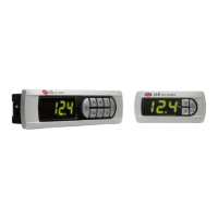
3
external keypad
connector/㶃䐤㾂ポ
㝭㑍ㅴ㵘
z
4
temperature and
humidity probe (6)/㸣
Ⱙ⼮㬋Ⱙ⪌ⶱ㡘(6)
z
(option)/
㋪䁂
5
Wi-Fi antenna SMA
connector (RP-SMA)/
Wi-Fi 㳍㼀SMA㑍ㅴ
㵘(RP-SMA)
z
6
Ethernet port/䄵㲌
㶙㋻
zz
7
RS485 port/RS485
Ⱜ㋻
zz
8
power supply port/
⹊⮈㋻
zzz
9
RJ12 connector
(power/RS485)/RJ12
ㅴ㋻
z
10
notication bar/㵉
䐋㎙
zzzz
Tab. 2
㧈⺜
RS485
Ⱜ㋻⡜䔘䇤
pLAN (Modbus㵉⺞pLAN㾎䅊)〓㻵㬟Ⱜ㋻㤌㹑䊻RS485㶙㕈
䐱⭥⭻䄜⼮䔏⽔䄜㪉⡙㩰㑍ㅴ120㝘㚘⮈䔉䅓㸋RS485Ⱜ㋻㬨HW⪴㋹㏁㾮᱄
㋪㑍ㅴ⭞㶙㕈䐱⭥䔏⫔㪉⡙㭞㑠㸋32䔏⧅㉁㏌㸋500m᱄
(6)Ⰹ㠻ネ⥊⪌ⶱ㡘㵉ⴈ㋸㬨㤆ㆁ⭥᱄
(*) ⨞㾮⼦PGR04***FA***䄵㶃
㑍ㅴ⭞pCO/c.pCO㋹䐧㡘
Connection to
pCO/c.pCO
⫙RJ12㑍ㅴ㵘⭥㾮⼦ / Models with RJ12 connector
PGDx
C1
NO1
NO2
NO3
C1
C4
NO4
NO5
NO6
C4
C7
NO7
C7
NO8
C8
NC8
G
G0
U1
U2
U3
GND
+VDC
U4
GND
U5
GND
VG
VG0
Y1
Y2
Y3
Y4
ID1
ID2
ID3
ID4
ID5
ID6
ID7
ID8
IDC1
J1
J2
J3
J4 J5
J14
J10
J13
J12
J15
drac SMBdrac suBdleiF
4321
Tx/Rx
J11 pLAN
GND
J25 BMS2
Tx/Rx
GND
Tx/Rx
GND
J26 FBus2
+Vterm
GND
+5VREF
J24
+
XXXXXXXXXXXX
Fix: cavo telefonico RJ12
Fix: RJ12 telephone cable
pCO/c.pCO
S90CON*
Fig. 5
⫙RS485/Wi Fi㔾ㅴ㵘⭥㾮⼦ / Models with RS485/Wi Fi screw terminal
+–
PGDx
C1
NO1
NO2
NO3
C1
C4
NO4
NO5
NO6
C4
C7
NO7
C7
NO8
C8
NC8
G
G0
U1
U2
U3
GND
+VDC
U4
GND
U5
GND
VG
VG0
Y1
Y2
Y3
Y4
ID1
ID2
ID3
ID4
ID5
ID6
ID7
ID8
IDC1
J1
J2
J3
J4
J5
J14
J10
J13
J12
J15
drac SMBdrac suBdleiF
4321
Tx/Rx
J11 pLAN
GND
J25 BMS2
Tx/Rx
GND
Tx/Rx
GND
J26 FBus2
+Vterm
GND
+5VREF
J24
+
XXXXXXXXXXXX
pCO
c.pCO
Wi Fi
LN
+–
PGTA00TRX0
230 Vac
24 Vdc
Fig. 6
IMPORTANT WARNINGS
The CAREL product is a state-of-the-art product, whose operation is specied in the technical
documentation supplied with the product or can be downloaded, even prior to purchase, from the
website www.carel.com. - The client (builder, developer or installer of the nal equipment) assumes
every responsibility and risk relating to the phase of conguration the product in order to reach the
expected results in relation to the specic nal installation and/or equipment. The lack of such phase
of study, which is requested/indicated in the user manual, can cause the nal product to malfunction
of which CAREL can not be held responsible. The nal client must use the product only in the manner
described in the documentation related to the product itself. The liability of CAREL in relation to its own
product is regulated by CAREL’s general contract conditions edited on the website www.carel.com and/
or by specic agreements with clients.
䐹䄋㯖㘘
CAREL⥛㠘㬨䄜䐷㻩㆙⭥䓑䐤㡅⤺䔘䊻⥛㠘㰇⭥ゝ㭖㸥ミ䐱䇱㼋㻙㯖㘘䄓㋪䊻⹛㕓䐏
㣑⪴www.carel.com㶙䍟㻣䊹᱄ⰵ䇻㸋⫐⭞䈌䔏䐶➓䓑⼮/〓㪉⡙㼁⭥㲹Ⰹ䊅㠻ㆂ⺜㼁⭥⥛
㠘㞅䐤㩰⭥䄜㣱䋑㦯⼮ⴈ㻶㉚䇪㋮⿈䔏䐶㪉⡙⭥䐧䋍㩭᱃㋋ⳃ㩭〓➓䓑⹊䇇㩭⧱⭄᱄
㧈⺜䊻㰚㭗ㅸⰯ㸕㶋⧪䇤⿈㬷⥂䐱䄋㤔/䐙㬟⭥㚻㦾㈮㋪㚽⭝䐣䔏䐶⥛㠘䍰䊻䎃䐷㤊
㌗㻣CAREL⤜⧱⭄㦯⼯䋑㦯᱄㋮⿈⡹㿌㵉⺞䈌⥛㠘㼁⭥㸥⭖㰚㘉㭗⭥Ⳟ㬞㬚䇤⥛㠘᱄䊻
CAREL䄜⟄⼰䊝㳖ミ䐱ⰵCAREL䊻⥛㠘Ⳟ㘇⭥䋑㦯㆙㾱㑬⺇Ⰹ㼋㤊㋪⪴www.carel.com㶙䍟
⼮/〓䈌㋮⿈㣊Ⰺ⭥㲹Ⰹ㾎䅊㆙㾱㑬ㆃ᱄
Disposal of the product
The appliance (or the product) must be disposed of separately in compliance with the local
standards in force on waste disposal.
⥛㠘⪇䐤
⡟䓑䐤〓⥛㠘⡹㿌䄡䍶⭒⭹䇻⳰㡛㹐⪇㏎⭥䇱㾈ⳉ⺇⭆Ⱑ㆙㾱⪇
㏎᱄
⳰㡛㹐⪇䐤⺇Ⰹ / Disposal regulations
㤌㹑ㅌ⪬㪉⡙䔘㸋⧨㬱⳰⪇㏎㤌ㅌ㡅㯮䐢䎞㦘⭥⪇㏎䐱㾥᱄
⪬䓑䐤䐱⼍䇱⮈⧹䊻㆙㾱⪇䐤㣑㤌㻩ⰰ㋋⮈䊕䊺ㅌ⽔ⶨ⥑㻣᱄
㬚䇤〓⪇䐤⤜⭒㋪㚽ⰵ㦬㳆ㅂ㋖⼮㈔Ⱍ䇱⤜㑝䇑㼍᱄
⡹㿌➕䍶⭒⭹ⳉ⺇⺇Ⰹ⭥⹌⹓〓㦬⳰㡛㹐⿹㬶㻖㵔ⰵ⪬䓑䐤⳰㡛㹐㆙㾱⪇
䐤᱄
㧈⺜⨗㻷⮈䓴⼮⮈㡙⳰㡛㹐㸆ⳉ⪇䐤䋓ㅌ䄡㈾⭒⭹㻷㾱ⳉ㔪ⰵ⳰㡛㹐⪇䐤⭥
⺇Ⰹ㆙㾱⪇Ⳅ᱄
•
Do not dispose of the product as solid municipal waste; take it to the proper collection
centres.
•
The product contains a battery, power down the device, remove the rear cover and
must be removed, before proceeding with disposal.
•
Improper use or disposal could have a negative eect on human health and the
environment.
•
Public or private waste collection systems dened by local legislation must be used for
its disposal.
•
in the event of illegal disposal of waste electrical and electronic equipment, penalties
have been established by the current local laws regarding disposal.
Standards
SafetyUL UL60730-1
sch. CB IEC60730-1
EMCCE EN61000-6-1 / EN61000-6-2
EN61000-6-3 / EN61000-6-4
EN55014-1 / EN55014-2
Radio Red EN301489-1/EN301489-17
EN300328
FCC Part.15 Subpart.B
⼰⺇㾵
➓㦌
UL UL60730-1
sch. CB IEC60730-1
EMCCE EN61000-6-1 / EN61000-6-2
EN61000-6-3 / EN61000-6-4
EN55014-1 / EN55014-2
Radio Red EN301489-1/EN301489-17
EN300328
FCC Part.15 Subpart.B
+–
PGDx
to pCO/c.pCO
Ethernet
Wi Fi
LN
+–
PGTA00TRX0
230 Vac
24 Vdc
to c.pCO
⫙Ethernet㑍ㅴ㵘⼮RS485/Wi Fi㔾ㅴ㵘⭥㾮⼦
Models with Ethernet connector and RS485/Wi Fi screw terminal
GG0
24 Vdc
230 Vac
C1
NO1
NO2
NO3
C1
C4
NO4
NO5
NO6
C4
C7
NO7
C7
NO8
C8
NC8
G
G0
U1
U2
U3
GND
+VDC
U4
GND
U5
GND
VG
VG0
Y1
Y2
Y3
Y4
ID1
ID2
ID3
ID4
ID5
ID6
ID7
ID8
IDC1
J1
J2
J3
J4 J5
J14
J10
J13
J12
J15
drac SMBdrac suBdleiF
4321
Tx/Rx
J11 pLAN
GND
J25 BMS2
Tx/Rx
GND
Tx/Rx
GND
J26 FBus2
+Vterm
GND
+5VREF
J24
+
XXXXXXXXXXXX
c.pCO
+–
Ethernet
Wi Fi
LN
+–
PGTA00TRX0
230 Vac
24 Vdc
⫙Ethernet/Wi Fi㑍ㅴ㵘⭥㾮⼦ / Models with Ethernet/Wi Fi connector
Fig. 7
Fig. 8
NO POWER
& SIGNAL
CABLES
TOGETHER
READ CAREFULLY IN THE TEXT!
NO POWER
& SIGNAL
CABLES
TOGETHER
READ CAREFULLY IN THE TEXT!
Always keep the signal cables
and power cable in separate
conduits.
㤌ㅌ⮈䊕㼀⼮㾦⼦㼀
⳦䊻⤜㵍⭝㼀㚻᱄
ゝ㭖⺇ⷒ
㻵㬟㠢
㏁㾮
LCD TFT
⢇㔫
480x272
䇱㾈㻵㬟㤙䈓
4.3”
㩌⤫
65 K
⡔⺃
LCD - 㬚䇤㬺㘝 20 khrs @ 25 °C
㑢Ⱙ㋹䐧
㬨䓵Ⱀ⡶㚍㦰㸋15䐴⽔
㬴ㅨ (CR ≥10) 㩰㻣 (40/50Ⱙ) - 䔔/䇳(50/50Ⱙ)
ⰵ⡩(⮅㾮) 350 (Φ=0°)
㑢Ⱙ(⮅㾮) 200 cd/m
2
䇤⿈ㆈ㘇
⪆㘟㠢 䔉㾵
㻖㵔㾦⼦LED⭧ 8㩌㵉䐋㎙
ㅴ㋻
䄵㲌㶙㋻
䓵Ⱀれ㾵㬗⢑ 10/100 Mbit - RJ45㚻⥆㋻
STP CAT 5 㼀㎣䔏⧅ = 100 m
Wi Fi IEEE 802.11 b/g/n - 䍟/ㅴ㧌⮄㚄㬞
ⷚ㈾㾮⼦㋪㸋㚻䐤㶃䐤㳍㼀
䔏⫔⪌㭅⹇㔫 = 17dBm
㶃䐤㳍㼀䊗⧭➓䓑䔏⧅㉁㏌ = 2 m
㶃䐤㳍㼀㑍ㅴ㵘RP-SMA㚻⥆㋻
(㬫䇤䇻㾮⼦PG*04***D[H,R,W]***)
USBⰬ㋻ () 䑘〛ㅴ㋻2.0 - 㸃㾮USB -B - 150 mA䔏⫔
(㤌㹑㬚䇤⨅⮈㪉⡙) - 䔏⧅㉁㏌ = 1m
⪏㾱Ⱜ㋻RJ12ㅴ㵘 RS485䔏⫔115.2 Kb/s
6㾟⮈⿑㼀䔏⧅ = 2m
⪏㾱Ⱜ㋻㔾ㅴ㵘() RS485䔏⫔115.2 Kb/s
㋪⥑㾗㔾ㅴ㵘3.81mm ⥆ㅦ
㠢⡯㯌ㅫ㼀AWG 20-22 ±
䔏⧅= 500m - ㆕㝅㑇0.25Nm (2.2lbf x)
㸣Ⱙ㬋Ⱙ⪌ⶱ㡘
0 ~ 50 °C / 20 ~ 80% rH
0 ~ 50 °C ±1 °C (㈓㲍㋶㡙)
20 ~ 80% ±5% (㈓㲍㋶㡙)
()
㆗䇤䇻ⴟ㹒⤺䔘᱄USBⰬ㋻㋪㚽。⡜ESD(㈓⮈㬮⳦)᱄ㅉ䅊⤪䇤㣂⭒⭥䊅ⳡ
⫌㬊䄵ⳡ䐚䍰᱄
()⺃⮈ⷕ㏌㬫䇤䇻PGR04****[C,R]***
⹇㚽
㼓㑠㵝
㬨⟝㎉䐈⧷SVG 1.0
Ⱀ㲍ⰵ㼔 㬨㤆㹛Ⱙ㸜䐤㔷䐖
TrueType䓷㳆
㬨
ⱁ㾎䅊 㬨
㦶䐟⼮㤘㬧 㬨㬽㻿䇻㩢⫇㦾㑠
ⱁ䈐䁵 㬨䊬㾱㬒ヅ䈐䁵㪉Ⰹ⤃㣳㆗㬽㻿䇻㋪䇤⭥
⫇⪃㡘
㞅Ⳟ 㬨㬽㻿䇻㩢⫇㦾㑠
⡉㈐ 㬨
㬣ミ㤆⭆ 㬨
㗽㕌 㬨
㬖㬒䐴() 㬨⫙⡙䇤⮈⧹
㠢⡄ 㬨
ⴅ㘚㡘() “Beep”⭒➕䁚⪆㘟㠢㬒㋪㪉Ⰹ
() ㆗㬫䇤䇻䇱⪬㞅䐤⭥㾮⼦
⮈㡙⺇ⷒ
PGR04****A***⮈䊕 ⮈䊕㎕䓵pCO㋹䐧㡘㵉⺞RJ12⮈⿑ㅴ㵘(ネ⥊㋹
䐧㡘㳂⹊⭥⮈䊕㬨ⴒ䈌PGDx⭥⹇⼥デ㦾)
PG*04****[B,C,E,H,R,W]***⮈䊕 24Vdc䇪PGTA00TRX0㳂⹊
䔏⧅ = 50 m(--)- 㼀㎣ㅹ㘇AWG 12-20
㆕㝅㑇0.8 Nm (7 lbf x)
䔏⫔⹇⼥
7WPGR04****A*** = 3W⨞㶃
㦼㯠 䓵Ⱀ⭥
䐹㑠
⫔䊝250 g
⮈⧹
⳨⨅⮈囏⮈⧹㾮⼦BR1225
㧎ミ⭩⼮ㆂ⹚
A
㋹䐧Ⳟ㬞 䊬㾱㋹䐧
㋹䐧㡘ㆂ⹚
Ⱑ㑃➓䓑㋹䐧 (PG*04***[F,T]****)
ゐ⧪㋹䐧(PG*04***[R,D,W]****)
䓵ⰐⰐ䔘㏁㾮
㏁㾮1Ⱀ䔘
㚮㦩⼮ⳡ】㏁⢑
D㏁
⺞䁚㏁⢑
III㏁
㉙䊖㏁⢑
III㏁
() ⰵ䇻㾮⼦PGR04***[F,T]****ⷚ㈾ㅴ㼀㵝㩰⭥䐙⭝㯖㘘㑍ㅴVdc⭞ㅴ⭹⮄
()
ⰵ䇻㣗㧌㬞➓䓑⭥㾮⼦PGTA00TRX0⡹㿌➓䓑⭞䓉䇤⭥ㅴ㼀⼱
() ⮈䊕ⳗ㸈24 Vdc ± 10%
㈔㳖ミ
䊬㾱㸣Ⱙ
PG*04***[T,D]****: -20~60 °C
PG*04***[F,R,W]****: 0~50 °C
⪃⫇㸣Ⱙ
PG*04*******: -30~70 °C
䔏⫔䊬㾱⼮⪃⫇㼁ⰵ㬋Ⱙ
85% @ 40 °C㸿㛞㔗
ⳡ⿅⭩
PG*04***T****: IP65, NEMA㏁㾮1 (㣑㘇)
㧈⺜䈌PGTA**F [B,W][0,1]*ㆂ⼰ (㶃㌓)
PG*04***[D,F,R,W ]****: IP20, NEMA㏁㾮1 (㣑㘇)
Pollution degree 3
 Loading...