The provided document is a service manual for the BINKS SMARTHP Pump System, manufactured by Carlisle Fluid Technologies. This manual, identified as 77-3333 R1.0, details the installation, operation, and maintenance of the Smart HP Local Control Unit + Inverter and associated pump models.
Function Description
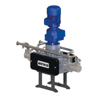
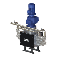
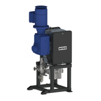
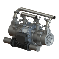
The BINKS SMARTHP Pump System is an electric high-pressure pump system designed for the supply and circulation of coating materials under pressure. It is intended for use with non-flammable materials. The system utilizes a Smart HP Local Control Unit + Inverter for dynamic adjustment of pump speed to maintain a set pressure, responding to changes in system fluid flow demand (variable material usage). This "Smart Mode" (closed loop) operation ensures efficient and consistent material delivery. The system includes various safety features and interlocks to ensure safe operation.
Important Technical Specifications
The manual outlines three primary pump models: E10-280, E14-210, and E20-140, each with specific performance characteristics and shaft/outlet configurations.
Pump Models and Specifications:
-
E10-280:
- 10 L/Min Max.
- 280 Bar Max.
- Available with Nitrided Shaft (Left Hand Fluid Outlet: 104255-LH, Right Hand Fluid Outlet: 104255-RH)
- Available with Ceramic Shaft (Left Hand Fluid Outlet: 104256-LH, Right Hand Fluid Outlet: 104256-RH)
-
E14-210:
- 14 L/Min Max.
- 210 Bar Max.
- Available with Nitrided Shaft (Left Hand Fluid Outlet: 104257-LH, Right Hand Fluid Outlet: 104257-RH)
- Available with Ceramic Shaft (Left Hand Fluid Outlet: 104258-LH, Right Hand Fluid Outlet: 104258-RH)
-
E20-140:
- 20 L/Min Max.
- 140 Bar Max.
- Available with Nitrided Shaft (Left Hand Fluid Outlet: 104259-LH, Right Hand Fluid Outlet: 104259-RH)
- Available with Ceramic Shaft (Left Hand Fluid Outlet: 104260-LH, Right Hand Fluid Outlet: 104260-RH)
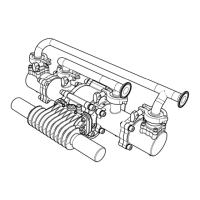
Dimensions and Mounting Details (Pump System):
- Overall Height: 2044 mm [80.5 inches] (including two lifting eyes on the center of gravity if needed)
- Inlet/Outlet Connections:
- Outlet: 2" NPT (E10-280, E14-210), 2½" NPT (E20-140)
- Inlet: 1½" NPT (all models)
- Mounting Footprint:
- Width (C): 329 mm [12.95 inches] (E10-280, E14-210), 323 mm [12.72 inches] (E20-140)
- Depth (D): 578 mm [22.76 inches] (all models)
- Earth Grounding: M6 HEX. Head screw for pump earth grounding. The pump frame must be wired to a suitable earth ground to prevent static build-up.
Required Inverter Settings (Pre-set):
- Maximum Hz Output: 60 HZ
- Minimum Hz Output: 0 Hz
- Acceleration Ramp: 2.5 Seconds
- Deceleration Ramp: 0.5 Seconds
- Rated Motor Power: 5.5 kW
- Rated Motor Current: 10.7 A
- Rated Motor Power Factor: 0.84
- Rated Motor Efficiency: 88%
- Rated Motor Frequency: 50 HZ
- Rated Motor Voltage: 400 V - DELTA
- Rated Motor Speed: 1460 RPM
Interconnecting Cable Kits (Item 3):
- CN-010A02-10: 10m Interconnecting Cable Kit (3 cables per pump)
- CN-010A02-15: 15m Interconnecting Cable Kit (3 cables per pump)
- CN-010A02-25: 25m Interconnecting Cable Kit (3 cables per pump)
- CN-010A02-50: 50m Interconnecting Cable Kit (3 cables per pump)
Usage Features
Installation:
- The pump must be securely mounted to a suitable flooring surface.
- Flexible hoses must be attached to inlet and outlet connections, with specified IDs for different working pressures:
- Suction: Ø75 I.D. [-1 to 2 bar], Ø50 I.D. [2 to 50 bar], or Ø38 I.D. [50 to 100 bar].
- Outlet: Ø38 I.D. (refer to pump manual for hose working pressure).
- Adequate air space around the pump is required for maintenance and motor cooling.
- The vent plug on top of the gearbox must be set to vent.
- Pump unit must be earthed using the grounding point at the base of the pump stand.
System Operation (Before Starting):
- Verify all electrical and mechanical connections are correct.
- Ensure all required interlocks are tested and operational.
- Confirm suitable material is available at the inlet port.
- Check that the control circuit is correctly wired for the pressure switch and that pressure sensors are calibrated correctly.
- Ensure all guarding is in place.
Pump Control Software Settings:
- Open loop pump speed to 6 HZ.
- Upper inlet pressure limit to 80 bar [1160 psi].
- Pump over pressure limit to pump model maximum (refer to pump manual).
- Pump over pressure timer to 3 seconds.
- Pump stop pressure to be set 10 bar [145psi] above pump maximum working pressure (refer to pump manual).
Pump Priming using Local Control Box (Pump Nudge):
- Set "pump function" selector switch on Smart HP control cabinet to OFF.
- Ensure material is available at the pump inlet (e.g., open inlet ball valve) and close the system outlet ball valve.
- Open the pump priming ball valve and place a suitable material collection device under its outlet.
- Rotate "pump function" dial on Smart HP control cabinet to maintenance mode.
- Use the "Nudge" switch on the local control cabinet to run the pump until material flows out of the priming valve without air contamination, then stop "Nudge" function.
- Close the priming ball valve and open the system ball valve.
- Switch the control panel to Open Loop (Flow Mode).
- Switch the system to Closed Loop (Production Mode) as required.
Smart Mode (Closed Loop):
- The pump automatically adjusts its speed to meet fluid flow demand, maintaining a constant set pressure despite variable material usage.
Maintenance Features
Regular Checks:
- Follow the maintenance schedule provided in the manual.
- Perform a packing check after the first four hours of operation.
Lubrication:
- Lubricate the pump packings set by adding approximately 100cc, or filling halfway up each packing nut, with compatible lubricant. The packings are accessible after removing one side of the fluid section removable cover assembly.
Spare Parts and Kits (Recommended Replacement):
Pump Assembly:
- Motor / Gearbox Assy: 195607 (1 per pump)
- Constant Velocity Cam: 194766 (2 per pump)
- Cam Follower Bearing: 193451 (4 per pump)
- Linear Bearing: 194813 (16 per pump)
- Fluid Section O-Ring Kit:
- 250823 (E10-280, 1 per pump)
- 250808 (E14-210, 1 per pump)
- 250755 (E20-140, 1 per pump)
- Fluid Section Packings and Seal Kit:
- 250824 (E10-280, 1 per pump)
- 250809 (E14-210, 1 per pump)
- 250756 (E20-140, 1 per pump)
- Fluid Section Overhaul Kit:
- 250825 (E10-280, 1 per pump)
- 250810 (E14-210, 1 per pump)
- 250767 (E20-140, 1 per pump)
- Main Bearing Overhaul Kit: 250770 (1 per pump)
- Pre-configured Inverter: CN-010C06 (1 per pump)
- Motor Encoder: CN-010C07 (1 per pump)
Main Control Cabinet:
- Interconnecting Cable Kits:
- CN-010A02-10 (10m, 1 kit per pump)
- CN-010A02-15 (15m, 1 kit per pump)
- CN-010A02-25 (25m, 1 kit per pump)
- CN-010A02-50 (50m, 1 kit per pump)
- Full Front Door Assembly: CN-010C04 (complete door including display, indicators, and switches)
- Fan Filter Replacement: CN-010C00 (pack of 5 filters)
- Simatic PC: CN-010A14 (with software pre-installed)
- PLC Complete Unit: CN-010A13 (with software pre-installed)
- High Pressure Smart Card: 194819 (with firmware pre-installed)
- Relay Replacement: CN-010C01 (pack of 5)
- Interface Terminal Block Assembly: CN-010C02 (contains fire alarm, volt-free, and two flow mode contacts)
- Power Supply Pack: CN-010C03 (contains both 24V and 5V power supplies)
- Front Panel Light Pack: CN-010C05 (includes all indicators for the front panel)
The manual emphasizes the importance of reading all instructions before operating the product and highlights the employer's responsibility to provide this information to the operator. It also includes a warranty policy and contact information for technical assistance and authorized distributors across various regions.