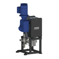
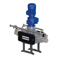
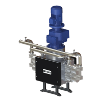
The EV2-15 Smart Pump is a fluid transfer device designed for use with both solvent and water-based materials in hazardous areas classified as Zone 1. It is available in several models tailored for different regions: 104274 (EU Model), 104272 (Japan Model), 104271 (USA Model), and 104282 (China Model). The pump is manufactured by Carlisle Fluid Technologies, a global leader in finishing technologies.
Function Description:
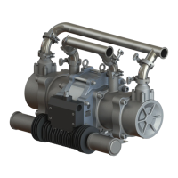
The EV2-15 Smart Pump is an electric pump designed for the supply and circulation of coating materials under pressure. It operates in a "Smart Mode" (Closed Loop Pressure Mode) where a return line 'back pressure' regulator dynamically adjusts the paint flow rate returning to the system paint tank, thereby maintaining a set pressure despite variable paint usage. This intelligent control system ensures consistent fluid pressure, which is crucial for high-quality finishing applications. The pump's design incorporates a gearbox and an AC induction electric motor to drive the fluid section.
Important Technical Specifications:
- Nominal Pump Stroke: 50mm [1.97 inches]
- Maximum Fluid Pressure (Smart Mode): 20 bar [290 psi]. When operating in "Open Loop (Flow Mode)", the maximum working pressure should be reduced by 2 bar [29 psi], meaning a maximum set pressure of 18 bar for 24/7 operation.
- Nominal Flow Volume / Cycle: 0.375 l/m [0.10 US gal/m]
- Fluid Output @ 20 Hz (10 cycles/min): 3.75 l/m [1.0 US gal/m]
- Fluid Output @ 80 Hz (40 cycles/min): 15 l/m [4.0 US gal/m]
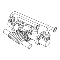
- Fluid Inlet Connection ('A'): 1" Sanitary
- Fluid Outlet Connection ('B'): 1" Sanitary
- Gearbox Ratio: 55:1
- Gearbox Oil (EU Model): Synthetic 220 (typically Agip Blasia S)
- AC Induction Electric Motor (EU Model):
- 400V 3PH 0.75 Kw @ 50Hz
- 4Pole 1400 RPM @50Hz
- EEx d IIB T3
- Rated 20 to 80 Hz (with thermistors)
- Total Weight of Pump (including electric motor): 135 kg [298 lbs]
- Max. Inlet Pressure: 2 bar [29 psi]
- Protection Level: Ex h IIB T4 Gb X (Pump), II 2 G Exd/Exde IIB T4 IP55 (Motor) CE0722, II 2 GD ck T4 (Gearbox).
- Inverter Settings:
- Maximum Hz Output: 80 Hz
- Minimum Hz Output: 20 Hz
- Acceleration Ramp: 5 Seconds
- Deceleration Ramp: 0.1 Seconds
- Rated Motor Power: 0.75 kW
- Rated Motor Current: 2A
- Rated Motor Power Factor: 0.81
- Rated Motor Efficiency: 78%
- Rated Motor Frequency: 50 Hz
- Rated Motor Voltage: 400 V
- Rated Motor Speed: 1440 RPM
Usage Features:
The pump is designed for ease of installation and operation.
- Installation: It must be installed in accordance with local regulations for hazardous areas, specifically Zone 1. Electrical connections require adherence to these regulations. A local control box is recommended for convenient Start/Stop functionality and as a junction box, while the main pump control panel should be in an electrically safe area. A pressure sensor connected to the outlet manifold port is critical for safety, set to stop the pump in case of system overpressure (e.g., a blocked paint filter), protecting the pump mechanics from overload. The maximum pressure setting for this sensor is 20 bar [305 psi].
- Motor Direction: The electric motor must be wired to ensure a clockwise direction of the cam.
- Motor Protection: The motor is equipped with PTC temperature sensors (Thermistors) that quickly change resistance upon reaching operating temperature. These must be connected to a suitable releasing device in the control panel to stop the motor in case of over-temperature.
- Hose Connections: Suitable flexible hoses are required: Ø28 I.D. for suction (-1 to 10 bar working pressure) and Ø25 I.D. for outlet (20 bar working pressure).
- Venting: The rubber pin in the vent plug on top of the gearbox must be removed to allow proper venting.
- Start-up Procedure: Before starting, all electrical and mechanical connections must be correct, interlocks tested, suitable material available, and the outlet connection unblocked. The pump speed should be set to a minimum frequency of 20 Hz to remove air from the circuit. After inspecting for leaks, the pump cycle rate is adjusted for the desired paint volume, and the system back pressure regulator is set for the desired fluid pressure.
- Smart Mode Operation: This mode intelligently manages fluid flow and pressure, adapting to variable paint usage to maintain a consistent set pressure.
Maintenance Features:
Regular maintenance is essential for the longevity and reliable operation of the EV2-15 Smart Pump. The working life of components is affected by abrasiveness of fluid pumped, pump duty cycle, and fluid pressure output. The main piston seal (162844) and cam follower (192392) are identified as components most affected and are recommended to be stocked as spare parts.
- General Maintenance: Always switch off the pump and secure against unintentional start-up before any maintenance.
- Daily Inspection: Check for any fluid leakage.
- Weekly Inspection: Check for excessive mechanical noise, excessive fluid pressure pulsation, and gearbox temperature (ensure it hasn't been activated).
- 3 Monthly Maintenance:
- Apply 8 strokes of standard 'cartridge' grease (502373) to cam follower bearings.
- Check oil level within the gearbox.
- Check the condition of the gearbox (especially for shaft seals leaking).
- Grease the main shaft bearing with 502375 grease.
- 6 Monthly Maintenance:
- Inspect Linear Bearings, Rod, Cam, and Cam followers for excessive wear; replace if necessary.
- Grease the top carriages with 502375 grease.
- Inspect and replace Piston Seals / Bellows / Springs.
- Annually Maintenance:
- Inspect Piston & Outlet Ball Checks.
- Inspect Linear Guide Bearing and Guide Rails for excessive wear; replace as necessary.
- Inspect Cam and Cam followers for excessive wear; replace if necessary.
- Every 5 Years Maintenance: Replace main shaft bearings, Linear Guide Bearings, Guide Rails, and Cams if excessive wear is observed.
- Grease Type: Use only 502375 (KP2N-20 DIN 51825) Grease for Cam Follower Bearing.
- Gearbox Maintenance:
- Every 2000 hours, verify the condition of oil seals and gaskets.
- Check oil level.
- If seals leak or oil level is reduced, the affected seal and oil need replacement, possibly a general overhaul.
- The unit must be drained, maintained, and refilled with oil.
- General overhauls must be performed by authorized ATEX certified service personnel.
- Oil changes require a suitable container for draining. Warm oil (40-50°C) facilitates draining.
- After filling with fresh oil, refit level and drain plugs and clean up any spillage.
- Motor Maintenance:
- Maintenance of Ex Motors must comply with EN 60079-17 standard.
- Electrical connections must be locked to avoid resistance-increases and overheating.
- Insulation air-distance and surface-distance between conductors must meet standards.
- All screws used to assemble motor parts and terminal box must be completely tightened.
- Replacement of seals and components for cable entry must use spare parts provided by the manufacturer.
- Ex joint surfaces must not be machined and must be clean to avoid corrosion or water entry.
- Gearbox Long Term Storage: If the gearbox is inactive for nine months or more, it must be prepared and stored according to specific guidance to prevent internal corrosion and early failure. This includes ensuring the sealing band in the vent plug is removed, and a warning label indicating the gearbox has been filled with a compatible polyglycol synthetic oil (lubricant type, viscosity, and quantity detailed on the gearbox serial plate). For storage up to three years, relative humidity should be less than 50%. If stored for more than two years, the lubricant should be replaced before use.
Fault Finding:
The manual provides a fault-finding guide for both mechanics and the fluid section, outlining symptoms, possible causes, and remedies.
- Mechanics Faults:
- Gearbox Output shaft does not rotate: Drive between shafts interrupted (remedy: return unit for repair/replace gearbox).
- Gearbox Oil leaking: From gear unit cover (defective gasket, remedy: retighten screws/return gearbox); from motor flange (defective gasket, remedy: return gearbox); from gear unit flange (gear unit not ventilated, remedy: check vent/transportation plug); from output oil seal (defective gasket, remedy: return gearbox).
- Gearbox Oil leaking from ventilator: Unit overfilled with oil (remedy: check and correct oil level).
- Cam Followers bearing generating heat/noise: Bearing needs lubrication (remedy: grease bearing/replace if damaged); spring tension insufficient (remedy: check/replace springs).
- Carriage does not maintain contact with cam; Noisy Changeover: Fluid seal friction or movement prevented (remedy: check fluid section - clean/replace piston seals, check piston surface, check for damage, check outlet cylinder bores are not filled with settled out residue).
- Fluid Section Faults:
- Pump will not 'Prime': Air entering suction hose/manifold (remedy: check o-rings and hose connections); worn piston seals (remedy: replace piston seals); ball checks not seating correctly (remedy: inspect, clean/replace balls and seats).
- Pump will not run: No power (remedy: check electrical supply); inverter unit or safety interlocks 'tripped' (remedy: check inverter and fault conditions).
- Pump runs, but lack of pressure: Worn piston seals (remedy: replace piston seals); worn balls and/or seats (remedy: inspect, clean/replace balls and seats); damaged PRV seat (remedy: check PRV seating faces for damage, see separate PRV service manual).
- Paint leaking from inside cover: Bellows seal failure (remedy: replace bellows seal, check piston seal, replace as necessary).
- Excessive Pressure Pulsation: Ball checks not seating correctly (remedy: inspect, clean/replace balls and seats); main shaft bearings worn (remedy: inspect, clean/replace main bearings); cam profile worn down (remedy: replace cam); cam direction incorrect (remedy: remove shaft assembly and rebuild following procedure on page 19).
Testing and Lubrication after Major Overhaul:
A warning is issued to wait until the unit has cooled sufficiently after stopping and isolation. Qualified personnel should perform testing and lubrication.
- Connect pump to paint system.
- Connect electric motor to a suitable electrical supply.
- Fit the gearbox vent plug, or remove rubber bung.
- Turn on paint system and set back pressure regulator to zero.
- Turn the pump on at the local isolation mounted switch.
- Allow the pump to run for about 10 minutes between 60 to 80Hz to ensure any trapped air is correctly vented.
- Check for any leaks and mechanical noises.
- Remove paint from the system if needed to lower system pressure.
- While running, apply 8 strokes of standard 'cartridge' grease gun (502373) to cam follower bearings.
- While running, apply 40 strokes of grease gun on a new bearing and 6 pumps on a bearing in current use to main shaft bearing.
- Run the pump at 20 cycles/min [40 Hz] and increase the back pressure to 10 bar and run for 1 hour.
- Check for any leaks and mechanical noises.
Fluid Drain Down:
Always wear protective eyewear, gloves, clothing, and a respirator as recommended by the fluid and solvent manufacturer.
- Stop the pump (turn off the electric motor).
- Isolate the paint supply and place a suitable container underneath the hose to prevent spillage.
- Disconnect the inlet & outlet hoses and position securely into a suitable container.
- Start the pump and run at slow speed [20Hz] for 1 minute.
- The pump will now have most of the paint removed; however, some material will remain within the fluid cylinders and manifolds.
- Stop the pump and place containers under fluid section and remove drain plugs.
- If required to finally remove any remaining paint from the pump, place the supply hose in a compatible solvent and run the pump until sufficiently clean.