ITALIANO
■
■
S
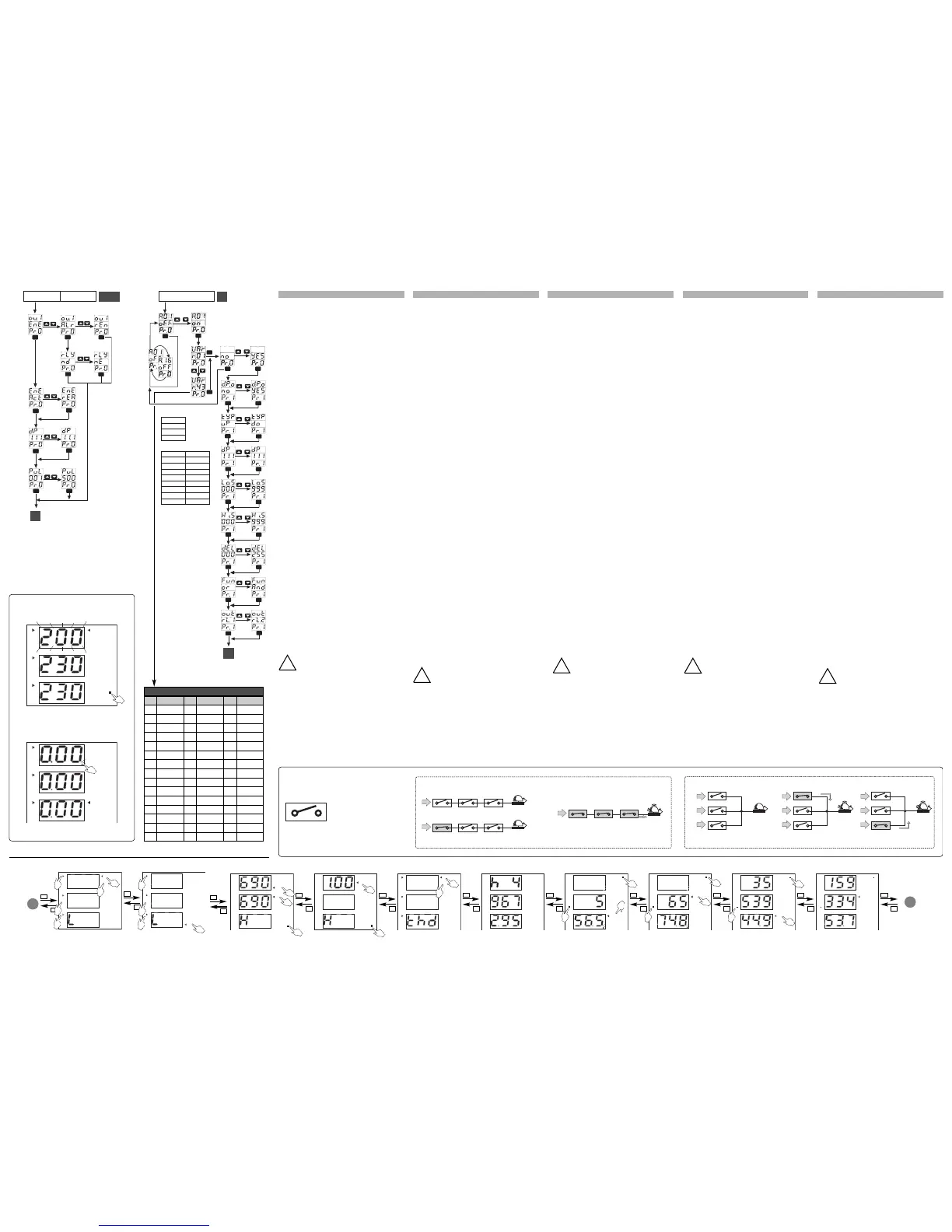
ETUP OUT 1 / OUT2
o
u.1 / ou.2 :
s
etup uscita 1 / 2, selezionare:
E
nE :
r
itrasmette il valore dell’energia attiva “Act” o
reattiva “rEA” mediante impulsi. “dP” seleziona il
p
unto decimale. “PuL” seleziona il numero di impulsi
p
er kWh/kvarh che si desidera generare da 0,01 a 500.
A
Lr :
a
ttiva l’uscita allarme. “
n
d
”
seleziona il relè nor-
m
almente diseccitato o normalmente eccitato “
n
E
”
.
rEn : attiva il controllo remoto (mediante connessione
s
eriale) dell’uscita 1/2.
■
■
ALARM SETUP MENU
A
.O1 :
“
oFF” disabilita l’allarme A.01, passando all’allar-
me successivo (fino a A.16). Le eventuali impostazioni
selezionate precedentemente rimangono memorizzate.
“
o
n
”
abilita l’allarme, quindi selezionare la variabile da
controllare:
V
Ar :
s
cegliere la variabile da controllare (vedi tabella “I”).
no, per passare direttamente alle impostazioni dell’al-
larme successivo
Y
ES,
p
er continuare la programmazione di tutti i
parametri relativa all’allarme in questione:
d
.P.o :
d
isattivazione dell’allarme all’accensione, “
n
o
”
p
er disattivare la funzione o “
Y
ES
”
per attivarla.
tYP : seleziona il tipo di allarme: in salita (uP) o in
d
iscesa (
d
o
)
a finestra interno (
i
n
)
a finestra
esterno (
out).
d
P :
s
eleziona la posizione del punto decimale.
L
o.S :
s
eleziona il valore della soglia inferiore.
Hi.S : seleziona il valore della soglia superiore.
d
EL :
s
eleziona il tempo di ritardo all’attivazione da 0
a
255 secondi.
Fun : seleziona la funzione di OR o di AND
(
vedere riquadro in basso“AND/OR”).
out : seleziona il relè da attivare in caso di allarme
“rl.1” uscita relè 1 o “rl.2” uscita relè 2.
NOTE IMPOR
TANTI:
• L
a variabile misurata lampeggia se si trova in stato di
allarme (vedi figura “G” a sinistra: V L1, 200V). E’ pos-
sibile abbinare più allarmi alla stessa variabile, la prima
c
ondizione di allarme che si verificherà determinerà il
lampeggio del campo variabile. La spia “al” (•) indica
l’attivazione di una delle due uscite (relè o a collettore
aperto) nel caso siano selezionate come allarme.
• Qualora lo strumento abbia installato le due uscite digitali
(relè o a collettore aperto) è possibile gestire fino a 16 allar-
mi che possono essere abbinati all’uscita 1 e/o uscita 2.
• Se “var” o “W” sono negativi il punto decimale all’est-
rema destra lampeggia in corrispondenza della variabi-
le negativa (vedi figura “H” a sinistra).
• Qualora lo strumento visualizzi una potenza negativa ,
l’energia relativa non verrà in alcun modo conteggiata.
■
■
PRECAUZIONI DI SICUREZZA
Leggere attentamente il manuale di istr
uzioni.
Qualora
l’apparecchio venisse adoperato in un modo
non specificato dal costruttore, la protezione
prevista dall’apparecchio potrebbe essere com-
promessa.
Manutenzione: Per mantenere pulito lo stru-
mento usare un panno inumidito; non usare abrasivi o
solventi. Si consiglia di scollegar
e lo strumento prima di
eseguire la pulizia.
DEUTSCH
■
■
E
INSTELLUNG OUT 1 / OUT2
o
u.1 / ou.2 :
E
instellung Ausgang 1 / 2, wählen:
E
nE :
n
ochmalige Übertragung des Wertes der
W
irkenergie “Act” oder der Blindenergie “rEA” über
I
mpulse. “dP” Wahl des Dezimalpunkts “PuL” Wahl der
Anzahl von Impulse bei kWh/kvarh von 0,01 bis 500.
A
Lr :
A
larm-Ausgang Aktivierung. “
n
d
”
Wahl des
R
elaisstatus: normal unerregt oder normal erregt
“
nE”. rEn : Aktivierung des Fernkontrolle (über seriel-
l
e Schnittstelle) des 1 / 2 Ausgang.
■
■
E
INSTELLUNG ALARM MENU
A
.O1 :
“
oFF” Deaktivierung des Alarms A.01, und weiter
z
u den nächsten (bis zu A 16). Alle andere Einstellungen
bleiben gespeichert. “
on” Aktivierung des Alarms und
W
ahl der zukontrollierenden Größe:
V
Ar:
W
ahl der zu kontrollierenden Größe (siehe Tab. “ I”).
no, direkt zur Einstellung des nächsten Alarmes gehen
Y
ES,
a
lle weiteren Parameter des eingestellten
A
larmes programmieren.
d.P.o : Desaktivierung des Alarms bei Einschaltung, “no”
u
m diese Funktion zu deaktivieren oder “
Y
ES
”
um die
Funktion zu Aktivieren.
t
YP :
W
ahl des Typs des Alarms: Höchstwert des
A
larms (
u
P
)
oder Mindestwert des Alarms (
d
o
)
, int.
Fensteralarm (
in), ext. Fensteralarm (out).
d
P :
W
ahl der Position des Dezimalpunkts.
L
o.S :
W
ahl der Mindestschwellengrenze
Hi.S : Wahl der Hochstschwellengrenze
d
EL :
W
ahl Alarm-Einschaltverzögerung von 0 bis 255 Sek.
Fun: Wahl der OR oder AND Funktion (siehe die
“OR/AND” Abbildung hier unten) .
o
ut :
W
ahl ob Relais normal unerregt. “rl.1”
Relaisausgang 1 oder “rl.2” Relaisausgang 2.
WICHTIGE HINWEISE:
• Die gemessene Größe blinkt, wenn ein Alarm aktiviert ist
(
siehe Abb. “G” links: VL1, 200V). Es ist möglich mehr
als einen Alarm mit der selben Größe verbinden; wenn
d
er erste Alarm aktiviert ist, blinkt der Bereich der Größe.
Die “al” (•) LED bedeutet die Aktivieru
ng von einem der
z
wei Ausgänge (Relais oder offener Kollektor Ausgang).
• Wenn beide digital Ausgänge im Gerät vorhanden sind
(Relais oder off
ener Kollektor), ist es möglich bis zu 16
A
larme zu kontrollieren; die 16 Alarme können zu
Ausgang 1 und/oder Ausgang 2 verbunden sein.
• Wenn “var” oder “W negative sind, blinkt der Dezimal -
punkt Äußerst Rechts, entsprechend der negativen
Größe (siehe Abb. “H” links).
• Sollte negative Energie angezeigt werden, ist zu beach-
ten, dass diese nicht gezählt wird.
■
■
SICHERHEITSMAßNAHMEN
Die Betriebsanleitung aufmerksam lesen.
Sollte das
Gerät nicht gemäß der Herstellerangaben ver-
wendet werden, könnte der vom Gerät vorge-
sehene Schutz beeinträchtigt werden.
Wartung: Das Gerät mit einem feuchten Tuch reinigen;
keine Scheuer- oder Lösemittel verwenden. Das Gerät
vor der Reinigung ausschalten.
!
FRANÇAIS
■
■
R
ÉGLAGE OUT 1 / OUT2
o
u.1 / ou.2 :
r
églage sorties 1 / 2, sélectionner:
E
nE :
r
etransmission de la valeur de l'énergie active
“
Act” ou réactive “rEA” par impulsions. “dP” pour
s
électionner le point décimal. “PuL” pour sélectionner
le nombre d’impulsions par kWh/kvarh de 0,01 à 500.
A
Lr :
a
ctivation de la sortie d’alarme. “
n
d
”
sélection du
r
elais normalement ouvert ou le relais normalement
fermé “
nE”.
r
En :
a
ctivation du contrôle à distance (par connexion
s
érie) de la sortie 1-2.
■
■
M
ENU RÉGLAGE ALARME
A.O1 :
“oFF” désactivation de l’alarme A.01, en passant à
l
’alarme suivante (jusqu’à A 16). Tous les autres régla-
g
es restent mémorisés. “
o
n
”
: activation de l’alarme,
puis sélectionner la variable à contrôler:
V
Ar :
s
électionner la variable à contrôler (voir table “ I”).
no, pour aller directement au réglage du prochaine alarme.
YES, pour continuer la programmation de tous les aut-
r
es paramètres concernant l’alarme sélectionné:
d.P.o : desactiver l’alarme à l’allumage, “no” pour
d
esactiver la fonction ou “
Y
ES
”
pour l’activer.
tYP : sélectionner le type d’alarme: haute (uP) ou
basse (
do), alarme dans fenêtre (in), alarme fenêtre
e
xterieure (
o
ut
)
.
dP : sélection de la position du point décimal.
L
o.S :
s
élection valeur du point de consigne basse.
H
i.S :
s
élection valeur point de consigne haute.
dEL : sélection sur temporisation activée de 0 à 255 sec.
F
un :
s
élection fonction OR ou AND (voir la figure
“OR/AND” dessous).
out : sélection du relais à activer en cas d’alarme
S
ortie relais 1 “rl.1”. Sortie relais 2 “rl.2” .
R
EMARQUES IMPORTANTES:
•
L
a variable mesurée clignote indiquant l’activation
d’une alarme (voir figure “G” à gauche: VL1, 200V).
Une ou plusieurs alarmes peuvent être connectées à
la même variable, la première condition d’alarme fait
clignoter la gamme de la variable. L’activation d’une
des deux sorties (re
lais ou collecteur ouvert) est indi-
qué par le diode “al” (•) s’elles sont sélectionnées
comme alarme.
• Quand les deux sorties (relais ou collecteur ouvert) sont
installées dans l’appareil, on peut gérer jusqu’à 16 alar-
mes que peuvent être connectées à la sortie 1 et/ou 2.
• Si “var” ou “W sont négatives, le point décimal à droite
clignote en correspondance avec la variable négative (voir
figure “H” à gauche.
• Si l’appareil affiche une puissance négative, l'énergie
correspondante ne serait pas considerée.
■
■
MESURES DE SECURITE
Lire attentivement le manuel de l’utilisateur.
Si l’appareil est utilisé dans des conditions
differentes de celles spécifiées par le fabri-
cant, le niveau de protection prévu par l’instrument
peut être compromis.
Entretien: Pour nettoyer l’instrument, utiliser un chiffon
humide; ne pas utiliser d’abrasifs ou de solvants. Il faut
déconnecter le dispositif avant de pr
océder au nettoya
-
ge.
!
E
SPAÑOL
■
■
A
JUSTE OUT 1 / OUT2
o
u.1 / ou.2 :
a
juste salida 1 / 2, selección:
E
nE :
r
etransmisión del valor de la energía activa “Act”
o
reactiva “reA” mediante pulsos. “dP” selecciona el
p
unto decimal.
“PuL” selecciona el numero de pulsos para kWh/kvarh
d
e 0,01 a 500.
A
Lr :
a
ctiva la salida de alarma. “
n
d
”
selecciona el relé
normalmente desactivado o normalmente activado “nE”.
r
En :
a
ctiva el control remoto (mediante conexión en
s
erie) de la salida 1/2.
■
■
M
ENU AJUSTE DE ALARMA
A.O1 :
“oFF” desactiva la alarma A.01, y continua a la alar-
m
a siguente (hasta A 16). Todos los ajustes selecciona-
dos anteriormente permanecen en memoria.
“o
n
”
permite la habilitación de la alarma, después selec-
c
ionar la variable que debe ser controlada:
VAr : seleccionar la variable que debe ser controlada (ver
t
abla “I”).
n
o,
p
ara ajustar directamente la alarma
s
iguente.
YES, para continuar la programación de todos los
p
arámetros conectados a la alarma seleccionada:
d.P.o : desactivar la alarma al arranque, “no” para
d
esactivar la función o “
Y
ES
”
para activarla.
t
YP
:
selecciona el tipo de alarma: de máximo (
u
P
)
o
de mínimo (
do) alarma dentro de banda (in), alarma
f
uera de banda (
o
ut
)
.
d
P
:
selección de la posición del punto decimal.
Lo.S : selección del limite mínimo.
H
i.S
:
selección del limite máximo.
dEL : selección del retardo a la conexión (0 a 255 s).
Fun : selección de la función de OR o AND (ver tabla
“
AND/OR” abajo).
out : selección del relé que debe ser activado en
caso de alarma “rl 1” salida relé 1 o “rl.2” salida relé 2.
N
OTAS IMPORTANTES:
•
L
a variable medida parpadea en re
lación a una alarma
(
ver figura “G” a la izquierda: V L1, 200V). Es posible
conectar mas de una alarma a la misma variable, el
campo variable parpadea en relación a la primera alar-
m
a. El LED “al” (•) indica la activación de una de las
dos salidas (relé o a colector abierto) si son seleccio-
n
adas como alarma.
• Si las dos salidas digitales (relé o a colector abierto)
están instaladas en el equipo es posible la gestión de
hasta 16 alarmas que pueden ser conectadas a la salida
1 y/o 2.
• Si “var” o “W” son negativos, el punto decimal a la
derecha parpadea en correspondencia a la variable
negativa (ver figura “H” a la izquierda).
• Si el equipo indica una potencia negativa, la energía
correspondiente no será calculada.
■
■
NORMAS DE SEGURIDAD
Leer el manual y seguir atentamente las
instrucciones.
Si se utiliza el equipo de mane-
ra distinta de como indica el fabricante se
puede dañar la protección de la que esta provisto el ins-
trumento.
Mantenimiento: para tener el instrumento
limpio, limpiar periódicamente la carcasa con un trapo
un poco humedecido. No utilizar productos abrasivos o
disolventes. Desconectar el instrumento antes de lim-
piarlo.
!
G
H
•
•
!
a b c
d
d
AND
OR
I
ENGLISH
■
■
S
ETUP OUT 1 / OUT2
o
u.1 / ou.2 :
s
etup of output 1 / 2, select:
E
nE :
r
etransmits the value of the active energy “Act”
o
r the reactive one “rEA” by means of pulses. “dP”
s
elects the decimal point. “PuL” selects the number
of pulses per kWh/kvarh from 0,01 to 500.
A
Lr :
e
nables the alarm output. “
n
d
”
selects the nor-
m
ally disabled relay or the normally enabled one
“
nE”.
r
En :
a
ctivates the remote control (by means of serial
c
onnection) of the 1 / 2 output.
■
■
A
LARM SETUP MENU
A.O1 :
“oFF” disables the alarm A.01, moving to the
n
ext one (up to A.16). Any other previously selected
s
etting remains stored. “
o
n
”
enables the alarm, then
select the variable to be controlled:
V
Ar :
s
elect the variable to be controlled (see table “ I”).
no, to go straight to the settings of the next alarm.
YES, to continue the programming of all other para-
m
eters relating to the alarm being set:
d.P.o : disable the alarm at power on, “no” to disable
t
he function or “
Y
ES
”
to enable it.
tYP : select the alarm type: up (uP) or down (do),
in window alarm (
in), out window alarm (out).
d
P :
s
elect the position of the decimal point.
Lo.S : select the value of the low setpoint.
H
i.S :
s
elect the value of the high setpoint.
d
EL :
s
elect the delay time on activation from 0 to
255 seconds.
Fun : select the OR or AND function (see the
“
OR/AND” picture below)
o
ut :
s
elect the relay to be enabled in case of alarm.
“rl.1” relay output 1 or “rl.2” relay output 2.
IMPORTANT NOTES:
•
T
he measure
d variable blinks when an alarm occurs
(see figure “G” on the left: VL1, 200V). It’s possible to
link more than one alarm to the same variable, the
first alarm condition will make the variable range
blink. The “al” (•) LED shows the activation of one of
the two outputs (relay or open collector output) in
case they are selected as alarm.
• When both digital outputs are installed in the instrument
(relay or open collector), it’s possible to manage up to 16
alarms that can be linked to output 1 and/or output 2.
• If “var” or “W are negative, the decimal point on the very
right blinks in correspondence with the negative variable
(see figure “H” on the left).
• If the instrument displays a negative power, the rele-
vant energy will not be counted.
■
■
SAFETY PRECAUTIONS
Carefully read the instruction manual.
If the instru-
ment is used in a way which is not specified
by the builder,the protection may be impaired.
Maintenance: To keep the intrument clean,use
a damp cloth; do not use abrasives or solvents. We
suggest you to disconnect the instrument before clea-
ning it.
!
 Loading...