3
Each terminal plate assembly may be utilized with or without
overloads. For compressors without overloads, please be
sure adequate protection is supplied for all 3 phases of the
motor in the form of a circuit breaker or similar system. For
compressors with overloads, please refer to Table 2 and
referenced figures to ensure proper connection with the ap-
plicable overload system on the compressor.
Table 2 — Overload Systems
Hybrid Overload Wiring — 6-Pin Plate Assem-
bly for Universal Compressors
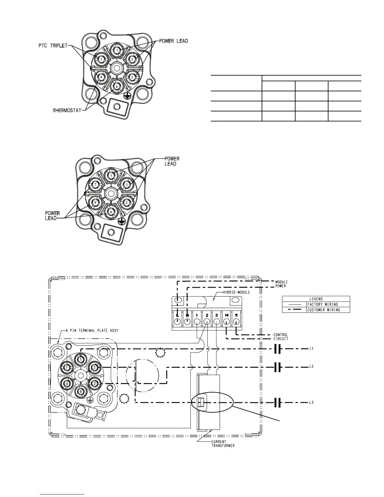
1. Connect one of the 2 control circuit leads to connection
14 located on top of the module. Connect the other
control circuit lead to connection 11 located on top of
the module. Use a fork terminal or stripped and tinned
wire to prevent fraying. See Fig. 8. Torque module con-
nections to 12 lb-in. (1.35 Nm) maximum.
2. Determine module power supply voltage by referring to
the 6th digit in the part number located on the left side
of module (06DANB****). The supply voltages are 115/
230 vac and 24 vac and correlate to digits B and C re-
spectively. Connect two module power leads to module
connections L and N using a fork terminal or stripped
and tinned wire to prevent fraying. Refer to module
front label for further power supply requirements.
Torque module connections to 12 lb-in. (1.35 Nm)
maximum.
3. Route one power lead (L3) through the current trans-
former (CT) as shown in Fig. 8. See detail in Fig. 9.
4. Once power lead L3 is routed through the CT, make
terminal plate connections as shown in Fig. 8. Refer to
Terminal Plate Wiring section for connection details.
Fig. 6 — 6-Pin Plate Assembly,
Universal Compressors
PTC — Positive Temperature Coefficient Thermistor
Fig. 7 — 6-Pin Plate Assembly,
Part Wind Compressors
TERMINAL PLATE
ARRANGEMENT
OVERLOAD SYSTEM OPTIONS
Hybrid
Service
Hybrid
Legacy
Bi-Metal
5 Pin (Fig. 5)
A, C or G in Digit 10
No Yes (Fig. 10) Yes (Fig. 11)
6 Pin (Fig. 6)
0, 1, 2 or 3 in Digit 10
Yes (Fig. 8) Yes (Fig. 10) Yes (Fig. 11)
6 Pin (Fig. 7)
B or D in Digit 10
No No Yes (Fig. 13)
Fig. 8 — Hybrid Overload Wiring
SEE DETAIL
IN FIG. 9

 Loading...


