7
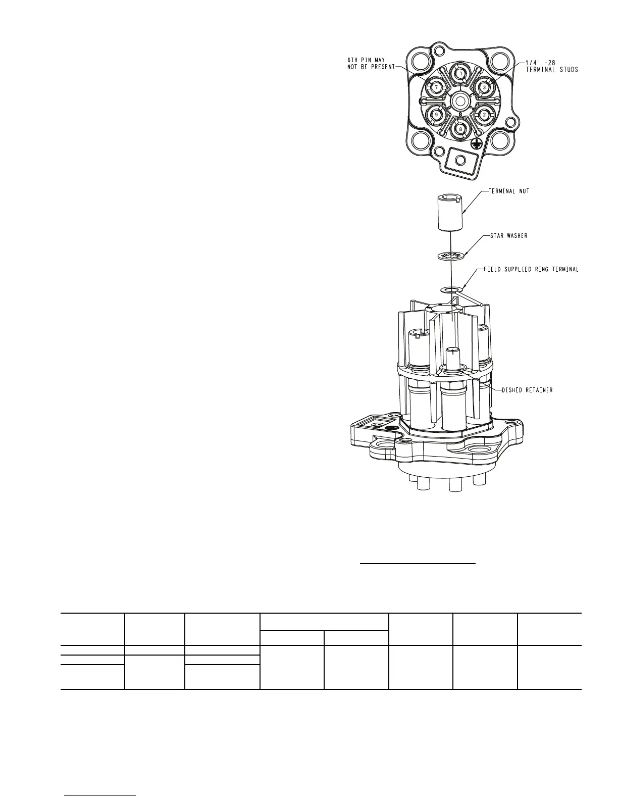
Terminal Plate Wiring
1. Field-supplied ring terminals are required to accommo-
date the
1
/
4
-in. -28 terminal studs.
2. With screwdriver, remove terminal nut and star washer
only on terminals needed to make connections applica-
ble to installed overload system. Leave dished retain-
er in place. See Fig. 14.
3. Apply all applicable power and control circuit leads to
the terminal studs per associated overload wiring dia-
gram. Reassemble star washers and extended slotted
terminal nuts. See Fig. 14.
4. Tighten extended terminal nuts to 30 lb-in. (3.4 Nm)
maximum.
OIL PRESSURE SAFETY SWITCH
1. All Carlyle 06D compressors are provided with connec-
tions for an oil pressure safety switch. The use of an oil
pressure safety switch can help prevent compressor
failures when loss of lubrication or loss of compressor
oil charge occurs. The use of an oil pressure safety
switch is required as a condition of warranty for 06D
compressors applied on systems in which two or more
06D compressors are connected in parallel. On units in
which single 06D compressors are applied, the use of
an oil pressure switch is recommended. See Fig. 1
through 4 for oil pressure safety switch connections.
2. Normal net oil pressure for 06D compressors is 18 to
34 psi (1.2 to 2.3 bar) above suction pressure. Net oil
pressure may vary depending on the lubricant type ap-
plied and operating conditions. Select a switch to close
the control circuit (at start-up) at a maximum of 12 psi
(0.83 bar) and open the control circuit at a minimum of
5 psi (0.35 bar). A time delay of not less than 30 sec-
onds nor more than 120 seconds is required for start-
up purposes. The switch must also be manually reset
when it trips.
3. Table 3 shows the oil pressure safety switches that
have been approved by Carlyle.
COOLING FANS
Cylinder head cooling fans are recommended for most appli-
cations that have saturated suction temperatures below 0° F.
Visit www.carlylecompressor.com for head cooling fan rec-
ommendations specific to the refrigerant type and operating
conditions of your application.
Table 3 — Oil Pressure Safety Switches
Fig. 14 — Terminal Plate Wiring Connections
CARLYLE
PART NO.
TIME DELAY CONNECTIONS
PRESSURE DIFFERENTIAL —
psi (bar) VOLTS
60 Hz
RESET
REMOTE
ALARM
CIRCUIT
CAPABILITY
Cut-in Cut-out
06DA660170 45 sec Electronic
8-11
(0.55-0.76)
4-8
(0.28-0.55)
115/230 Manual Yes
P529-2430
120 sec
1/4 in. Male Flares
P529-2410
36 in. Lg. Cap.
Tube 1/4 in. SAE
Nuts

 Loading...


