14
Reset function
4
2
1
1
1
3
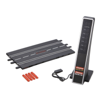
To restore the Control Unit to factory settings the Control Unit offers
a reset function.
Switch off the Control Unit and keep the “ESC/PACE CAR”
4
but-
ton pushed; switch on the ractrack and release the button again. All
previous settings for speed, braking performance, tank fuel capac-
ity, sound and lap counting will be restored to factory settings. The
cars´ settings will remain unaffected by this measure unless they are
placed on the racetrack.
Factory settings:
• speed = 10
• braking performance = 10
• tank capacity = 7
• sound = ON
• display of position for Autonomous and Pace Car = OFF
Energy-saving mode
After 20 minutes of non-usage the Control Unit switches to ener-
gy-saving mode and all displays such as Position Tower, Driver
Displays and Startlight are turned off. To reactivate the controller,
switch it off for 2 or 3 seconds, then switch it on again. All settings
will be kept.
Replacement of double
contact brushes and guide keel
1 2
43
In case the car is lifted, the rocker bar folds up slightly (fig.
1
).
For changing the guide keel or the double contact brushes the
rocker bar can be folded up widely according to fig.
2
.
3
For changing the guide keel and the double contact brushes the
guide keel should be removed first.
4
Afterwards both double contact brushes can be removed and
changed. Please take care that in stage one the upper contact
brush
4
a
is only pulled out partly and in stage two the double
contact brush is pulled out completely with the contact brush
4
b
For inserting please proceed the same way.
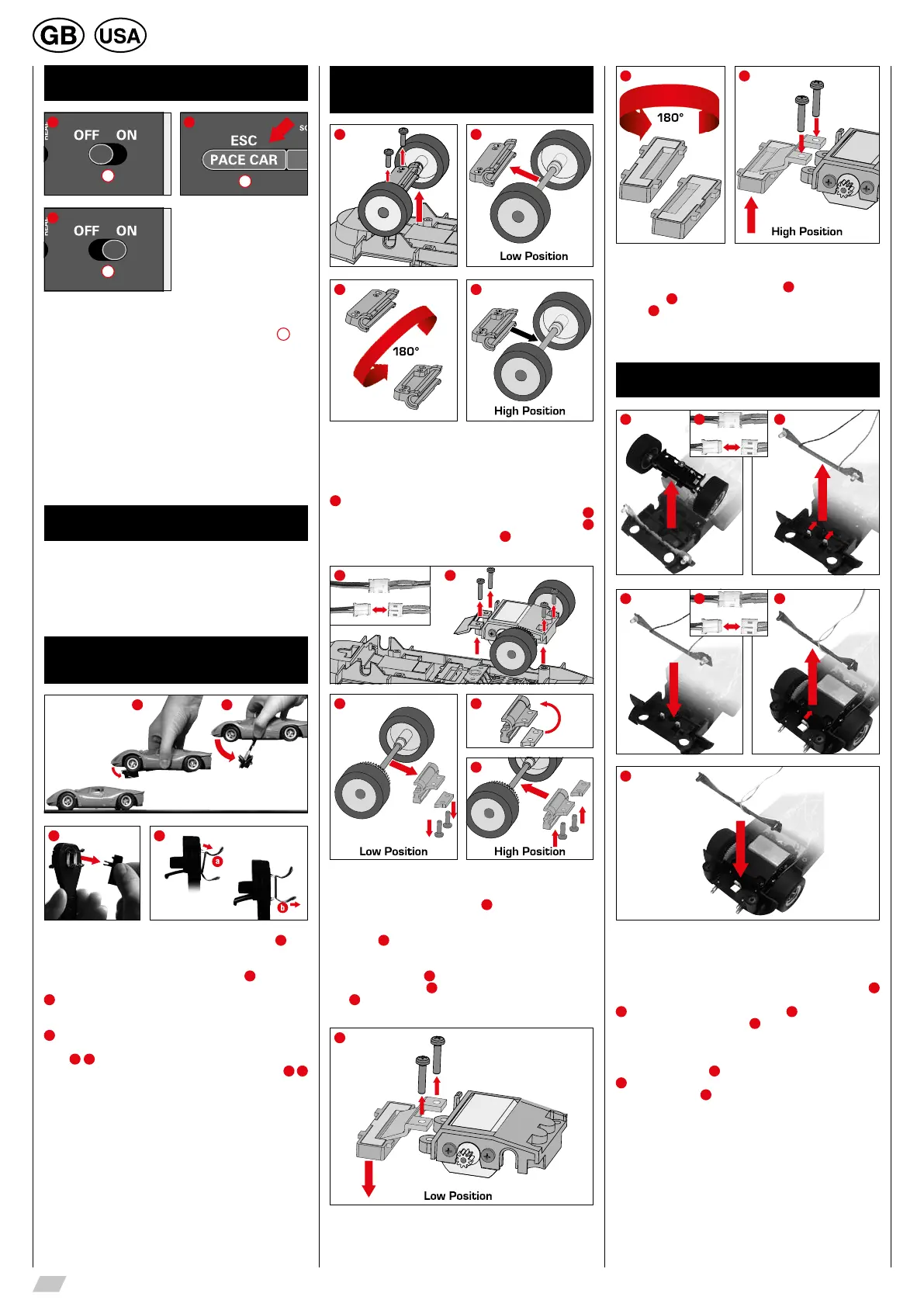
Height adjustment
car chassis
1 2
3 4
Before you can begin adjusting the chassis and the magnets it is
necessary to detach the car body from the vehicle. Remove the
mounting screws on the underside of the car and lift off the car body.
Adjusting the height of the front axle
1
Remove the two screws from the front axle mounting and detach
the entire front axle including the mounting from the chassis.
2
Detach the mounting from the axle, turn it through 180 degrees
3
and insert the axle back into the mounting
4
. Now you can return
the front axle and mounting unit to the chassis.
1 2
3 4
5
Adjusting the height of the rear axle
To simplify the procedure, carefully detach the plug connection bet-
ween the motor and the circuit board
1
. Remove the two screws
from the motor block unit and detach the magnet retainer from the
chassis. Now remove the two rear screws and detach the entire
motor block
2
.
Turn the motor block around and remove the two screws from the
rear axle mounting. Remove the spacer plates and the rear axle unit
including the mounting
3
. To adjust the height, place the spacer
plate in the motor block
4
and tighten the screws of the rear axle
unit.
5
.
1
2 3
Adjusting the central magnet
If required, the central magnet can also be adjusted. Remove the
magnet unit from the chassis in its entirety
1
, turn it horizontally by
180 degrees
2
and return it to the chassis. Then mount the magnet
retainer
3
and restore all plug connections.
Note: Height adjustment car chassis – Dependent on model
Changing the light board
1 32
4 65
7
ATTENTION! Depending on the model, the light boards might be
screwed tight.
Front light: To change the light boards unscrew the car’s upper
part from the chassis. Unscrew the front axle according to fig.
1
and remove the cables between the front light and the car board (fig.
2
). Slightly bend down the catch hook (fig.
3
) and pull up the light
board. Insert the light board (fig.
4
), until the catch hook latches
in. Screw in the front axle and fit the cables together according to
their colours.
Rear light: Remove the cables between the rear light and the car
board according to fig.
5
Slightly bend down the catch hook (fig.
6
) and pull up the light board. Insert the light board until the catch
hook latches in (fig.
7
) and fit the cables together according to
their colours.