11
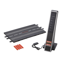
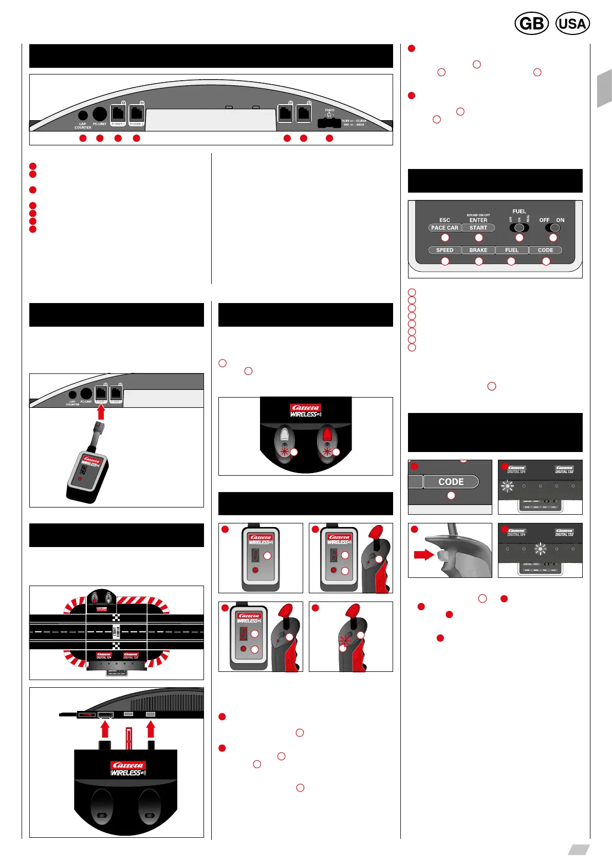
Connections (from left to right):
1
Connection for Lap Counter 20030342
2
Connection for Carrera AppConnect 20030369, PC-Unit or
Lap Counter 20030355
3
Connector 1 for speed controller, speed controller extension set
or WIRELESS+ receiver
4
Connector 2 for WIRELESS Tower
200
10108
5
Connector 3 for speed controller
6
Connector 4 for speed controller
7
Connection for DIGITAL 124 / DIGITAL 132 power supply
General information on connectors 1-4:
When a WIRELESS+ receiver is used, it must be plugged into con-
nector 1. Optionally a WIRELESS Tower 20010108 can be plugged
into connector 2. When only the WIRELESS+ receiver is used, con-
nector 2 is to be left empty.
Additional wired speed controllers may be plugged into connectors
3 and 4. Please note that these will use address 5 and 6 then.
Using the speed controller extension set 20030348 it has to be
plugged into connector 1. The cars´ addresses will be allocated as
follows:
• Speed controller extension set = address 1, 3 and 4
• connector 2 = address 2
• connector 3 = address 5
• connector 4 = address 6
Note:
a combination of WIRELESS and speed controller extension set is
not possible!
Please note that in DIGITAL 124 the number of cars is restricted
to four.
Connections Control Unit
1 52 63 74
Connecting the receiver
Connect the receiver according to the symbol to either of the two
sockets on the control unit which are marked Tower 1 and Tower 2.
For operating four WIRELESS+ speed controllers only one 2.4 GHz
receiver is required.
Symbols
Connecting the charging unit
The charging unit is connected at the rear of the control unit. To site
the charging unit at any other place on the track, an adapter unit
20030360 will be needed.
Rear view of the
control unit
Charging the speed controllers
Before first being used, the WIRELESS+ speed controllers should
be fully charged. Place the speed controllers in the charging station
and switch on the control unit. While the unit is charging, the LEDs
1
on the speed controllers will flash. When charging is completed,
the LEDs
1
will light up continuously.
When using a lithium polymer rechargeable battery, it is possible to
top up the speed controller at any time.
1 1
Binding process
2
SET
CHANNEL
1
2
3
1
SET
CHANNEL
1
4
2
1
3
SET
CHANNEL
1
2
3
Before the speed controller can be used to control the cars, it must
be “bound” to the receiver.
To do this, switch on the control unit.
1
The receiver indicates it is ready for operation by a revolving light
signal in the segment display
1
.
2
Push the “SET” button
2
once until the figure 1 appears in the seg-
ment display
1
. The number shown is then the address of the car.
Switch to the next address by further pressing the button.
Now press the binding button
3
on the top of the speed controller.
The speed controller signals a successful binding process with
flashing of the LED, while the receiver indicates it by revolving lights
in the segments. The binding process is now complete and the
speed controller is ready for use.
3
To bind the second speed controller, follow the same procedure.
Press the “SET” button
2
on the receiver twice, until the figure
2 appears
1
. Then press the binding button
3
on the second
speed controller.
4
To display the address set for the speed controller, press once on
the binding button
2
on the top of the speed controller.
The LED
1
will then flash, according to the address set.
If the speed controller is not actuated, it switches automatically after
about 20 seconds into energy-saving mode. The speed controller
can be reactivated by pressing the tappet or the lane-change button.
Control elements Control Unit
1
8
2
7
3
6
4
5
1
On/off switch
2
Switch for fuelling function
3
Button to start the race / acknowledge programming
4
Button for Pace Car / termination of programming
5
Button for setting basic speed
6
Button for setting braking performance
7
Button for setting fuel tank capacity
8
Programming button for cars
General operating information
Some buttons are assigned with different tasks. In order to set a
function you need to use key combinations. Any programming steps
can be cancelled with button
4
“ESC/PACE CAR″. You will find
further details in the course of this manual.
Encoding/programming
of cars to the according
speed controllers
8
1 2
1x
3 4
To encode a car place it on the track and swich on the Control Unit.
Press “Code” button once
8
, fig.
1
; the first LED starts to light,
fig.
2
. Then push lane-change-button once on the relevant speed
controller, fig.
3
. In case the car is equipped with lights they will
start to flash and the Control Unit´s LEDs 2-4 will light successively.
Once encoding has been carried out the middle LED lights perma-
nently (fig.
4
) and the car is allocated to the speed controller.
Note: This kind of encoding requires to only have the car on the
racetrack which shall be encoded.