EasyManua.ls Logo

Carrier 024-048 User Manual

Carrier 024-048
41 pages
To Next Page IconTo Next Page
Page #1 background imageLoading...
Page #1 background image
Service Manual
Table of Contents
Safety Considerations . . . . . . . . . . . . . . . . . . . . . . . . . . . . . . . . . . . . . 1
Introduction. . . . . . . . . . . . . . . . . . . . . . . . . . . . . . . . . . . . . . . . . . . . . 1
Installation Guideline . . . . . . . . . . . . . . . . . . . . . . . . . . . . . . . . . . . . . 2
Accessories . . . . . . . . . . . . . . . . . . . . . . . . . . . . . . . . . . . . . . . . . . . . . 2
Table 1 – Required Field-Installed Accessories for Air Conditioners
and Heat Pumps . . . . . . . . . . . . . . . . . . . . . . . . . . . . . . . . . . . . . . . 2
Low-Ambient Cooling Guideline . . . . . . . . . . . . . . . . . . . . . . . . . . . . 2
Cabinet Assembly . . . . . . . . . . . . . . . . . . . . . . . . . . . . . . . . . . . . . . . . 3
Electrical . . . . . . . . . . . . . . . . . . . . . . . . . . . . . . . . . . . . . . . . . . . . . . . 9
Table 2 – Defrost Control Speed-Up Timing Sequence . . . . . . . 14
Scroll Compressor. . . . . . . . . . . . . . . . . . . . . . . . . . . . . . . . . . . . . . . 14
Reciprocating Compressor . . . . . . . . . . . . . . . . . . . . . . . . . . . . . . . . 16
Refrigeration System . . . . . . . . . . . . . . . . . . . . . . . . . . . . . . . . . . . . 20
Table 3 – Compressor Information . . . . . . . . . . . . . . . . . . . . . . . 21
Table 4 – Piston/TXV Table . . . . . . . . . . . . . . . . . . . . . . . . . . . . 23
Refrigeration System Repair. . . . . . . . . . . . . . . . . . . . . . . . . . . . . . . 23
Table 5 – Minimum Airflow for Safe Electric Heater Operation 28
Table 6 – Superheat Charging . . . . . . . . . . . . . . . . . . . . . . . . . . . 28
Table 7 – 13.4 SEER2 Required Subcooling. . . . . . . . . . . . . . . . 29
ECM Fan Motor Troubleshooting . . . . . . . . . . . . . . . . . . . . . . . . . . 30
Care and Maintenance . . . . . . . . . . . . . . . . . . . . . . . . . . . . . . . . . . . 37
Table 8 – Pressure vs. Temperature Chart - R-410A Refrigerant38
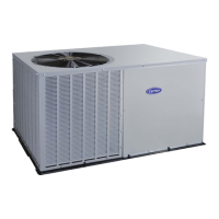
024-048 A/C and 024-036 Heat Pump
A10165
060 A/C and 042-060 Heat Pump
A150067
Fig. 1 – A/C and Heat Pump
Safety Considerations
Installation, service, and repair of these units should be attempted only
by trained service technicians familiar with standard service instruction
and training material.
All equipment should be installed in accordance with accepted practices
and unit Installation Instructions, and in compliance with all national and
local codes. Power should be turned off when servicing or repairing
electrical components. Extreme caution should be observed when
troubleshooting electrical components with power on. Observe all
warning notices posted on equipment and in instructions or manuals.
Refrigeration systems contain refrigerant under pressure. Extreme
caution should be observed when handling refrigerants. Wear safety
glasses and gloves to prevent personal injury. During normal system
operations, some components are hot and can cause burns. Rotating fan
blades can cause personal injury. Appropriate safety considerations are
posted throughout this manual where potentially dangerous techniques
are addressed.
Follow all safety codes. Wear safety glasses, protective clothing, and
work gloves. Have a fire extinguisher available. Read these instructions
thoroughly and follow all warnings or cautions included in literature and
attached to the unit. Consult local building codes, the current editions of
the National Electrical Code (NEC) NFPA 70 and NFPA
90B-Installation Warm Air Heating and A/C Systems (Residential).
In Canada refer to the current editions of the Canadian Electrical Code
CSA C22.1.
Introduction
This document provides required system information necessary to
install, service, repair or maintain the small package products (SPP) air
conditioners and heat pumps using R-410A refrigerant.
Refer to the unit Product Data/Technical specifications for rating
information, electrical data, required clearances, additional component
Residential Mobile Home Small Package Products
Air Conditioners and Heat Pumps
Using R-410A Refrigerant
WARNING
!
UNIT OPERATION AND SAFETY HAZARD
Failure to follow this warning could result in personal injury or
equipment damage.
R-410A systems operate at higher pressures than standard R-22
systems. Do not use R-22 service equipment or components on these
R-410A units. Ensure service equipment is rated for R-410A.
WARNING
!
PERSONAL INJURY AND PROPERTY DAMAGE
HAZARD
For continued performance, reliability, and safety, the only approved
accessories and replacement parts are those specified by the equipment
manufacturer. The use of non-manufacturer approved parts and
accessories could invalidate the equipment limited warranty and result
in fire risk, equipment malfunction, and failure. Please review
manufacturer's instructions and replacement part catalogs available
from your equipment supplier.
Question and Answer IconNeed help?

Do you have a question about the Carrier 024-048 and is the answer not in the manual?

Carrier 024-048 Specifications

General IconGeneral
BrandCarrier
Model024-048
CategoryAir Conditioner
LanguageEnglish

Summary

Installation Guideline

Residential New Construction

Details installation specifications for the residential new construction market.

Add-On Replacement (Retrofit)

Covers installation requirements for the add-on replacement/retrofit market.

Accessories

Accessory Descriptions

Provides descriptions for various field-installed accessories for air conditioners and heat pumps.

Low-Ambient Cooling Guideline

Specifies minimum operating temperatures for cooling mode with accessories installed.

Cabinet Assembly

Basic Cabinet Designs

Describes the standard cabinet construction and panel removal for maintenance.

Door Gasket/Insulation

Details requirements for replacement gaskets and insulation materials for cabinet panels.

Access Compressor Or Other Internal Cabinet Components

Labeling

Electrical

Electrical Shock Hazard

Warning about electrical hazards and safety precautions for trained personnel.

Aluminum Wire

Guidelines for using aluminum wire in branch circuits, including NEC compliance.

Contactor

Explanation of contactor function, troubleshooting steps, and checking continuity.

Capacitor

Details on capacitor function, testing procedures, and safety warnings.

Cycle Protector

Crankcase Heater

Pressure Switches

Defrost Thermostats

Defrost Control Board

Defrost Control

Explains the demand defrost control features, initial intervals, and automatic adjustment.

Cooling Sequence of Operation

Describes the operation of the defrost control in cooling mode.

Heating Sequence of Operation

Explains how the defrost control operates when the unit is in heating mode.

Defrost Sequence

Details the defrost mode operation, timing, and termination conditions.

Troubleshooting

Defrost Speedup

Procedures to test the defrost function by forcing a defrost cycle using speed-up pins.

Scroll Compressor

Scroll Gas Flow

Explains the process of gas compression within a scroll compressor.

Compressor Failures

Mechanical Failures

Discusses compressor failures related to mechanical issues, excluding electrical circuits.

Locked Rotor

Describes compressor failure due to motor drawing locked rotor current and cycling off internal protection.

Runs, Does Not Pump

Explains compressor failure where motor runs but does not pump refrigerant, causing overheating.

Noisy Compressor

Covers common causes of compressor noise, including internal and external factors.

Electrical Failures

Details compressor failures where the motor does not run despite normal external systems.

Single-Phase Motors

Provides steps to identify compressor motor terminals (C, S, R) using an ohmmeter.

Single-Phase Motor Electrical Tests

Open Circuit

Procedure to test for breaks in motor winding internal wires, indicating an open circuit.

Ground Circuit

Method to check if a wire has broken or contacted the shell, causing a short to ground.

Reciprocating Compressor

Compressor Performance Issues

Runs, Does Not Pump, High-To-Low Side Leak

Explains compressor failure where hot discharge gas returns to shell, causing overheating.

Runs and Pumps, Low Capacity

Describes capacity loss due to damaged internal compressor parts like valves.

Compressor Leaks

Discusses detecting and repairing leaks at compressor shell welds or fittings.

Short Circuit

Procedure to test for wires breaking insulation and shorting windings due to internal wire contact.

System Clean-Up After Burnout

Compressor Removal and Replacement

Outdoor Fan Adjustment

Fan Motor

Details the function, enclosed nature, and replacement procedures for the outdoor fan motor.

Low-Voltage Terminals

Refrigeration System

Refrigerant

Discusses R-410A refrigerant properties, pressure, and system requirements for handling.

Compressor Oil

Details the hygroscopic nature of POE/PVE oil used in R-410A systems and precautions.

Brazing

Provides basic points and rules for brazing techniques in refrigeration systems.

Reversing Valve

Explains the reversing valve function, troubleshooting, and replacement procedures.

Refrigerant System Components

Liquid Line Filter Drier

Describes the function of liquid line filter driers specifically designed for R-410A refrigerant.

Suction Line Filter Drier

Details the use and installation of suction line filter driers for acid removal in R-410A systems.

Accumulator

Explains the accumulator's role in storing liquid refrigerant and preventing flood-back in heat pump heating mode.

Thermostatic Expansion Valve (TXV)

TXV Operation

Describes how the TXV adjusts refrigerant flow to maintain preset superheat temperature.

Piston Body Cleaning or Replacement

Refrigerant Flow Control Devices

Liquid Tube Strainer/Filter

Explains the protection provided by strainers and filter driers for TXVs.

Piston Body Cleaning or Replacement

Details the procedure for cleaning or replacing a piston in the flow control device.

Coil Removal

Compressor Removal and Replacement

Evacuation

Deep Vacuum Method

Describes using a vacuum pump and gauge to achieve a deep vacuum for system evacuation.

Triple Evacuation Method

Details the procedure for evacuating a system using nitrogen to remove moisture.

Check Charge

Troubleshooting with SuperHeat

Basic Diagnostics

Steps to verify indoor airflow and check subcooling before troubleshooting superheat.

Low Superheat with Normal or Low Suction Pressure

Addresses low superheat conditions with normal or low suction pressure in TXV systems.

Low Superheat with High Suction Pressure

Addresses low superheat conditions with high suction pressure, typically caused by component failure.

High Superheat with Normal or Low Pressure

Discusses high superheat conditions with normal or low suction pressure, indicating restrictions.

High Superheat with Normal or High Suction Pressure

Covers high superheat with normal or high suction pressure, often due to application issues.

Hunting Superheat

Describes hunting superheat, an issue with TXV systems typically related to application or valve imbalance.

Indoor Airflow and Airflow Adjustments

Refrigerant Charge

No Charge

Procedure for evacuating the system and weighing in the specified amount of refrigerant.

Low Charge Cooling

Steps for checking refrigerant charge in cooling mode using superheat for fixed metering devices.

TXV Metering Device

Procedure for checking refrigerant charge using subcooling for TXV metering devices.

Heating Mode

Related product manuals