ii
62--11052
PARAGRAPH NUMBER
Page
3.8 COMPRESSOR RUNNING GEAR REASSEMBLY 3--6........................................
3.8.1 Seal End Main Bearings 3--6............................................................
3.8.2 Pistons, Rods, and Rings 3--6...........................................................
3.8.3 Crankshaft and Seal End Thrust Washer 3--7.............................................
3.8.4 Bottom Plate, Strainer, and Connecting Rod Caps 3--7.....................................
3.9 SUCTION STRAINER 3--7.................................................................
3.10 ADDING OIL 3--7.........................................................................
3.11 INSTALLING COMPRESSOR 3--7..........................................................
LIST OF ILLUSTRATIONS
FIGURE NUMBER Page
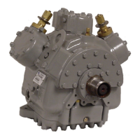
Figure 1--1. Model 05G Compressor 1--2............................................................
Figure 1--2. Suction & Discharge Valve 1--3..........................................................
Figure 1--3. Oil Pump 1--3.........................................................................
Figure 1--4. Shaft Seal Reservoir 1--3...............................................................
Figure 1--5. Compressor Unloader 1--4.............................................................
Figure 1--6. Electric--Operated Unloader--Unloaded Operation 1--4......................................
Figure 1--7. Electric--Operated Unloader--Loaded Operation 1--5........................................
Figure 1--8. Pressure--Operated Unloader Loaded Operation 1--5.......................................
Figure 1--9. Pressure--Operated Unloader --Unloaded Operation 1--5....................................
Figure 2--1. Removal of Piston Plug 2--1.............................................................
Figure 2--2. Oil Level in Sight Glass 2--2.............................................................
Figure 3--1. Shaft Seal Reservoir 3--1...............................................................
Figure 3--2. Cylinder Head & Valve Plate 3--2........................................................
Figure 3--3. Installing Suction Valves 3--2............................................................
Figure 3--4. Checking Suction Valve 3--2.............................................................
Figure 3--5. Oil Pump and Bearing Head Assembly 3--3...............................................
Figure 3--6. Oil Pump 3--3.........................................................................
Figure 3--7. Shaft Seal 3--3........................................................................
Figure 3--8. Shaft Seal Removal 3--4................................................................
Figure 3--9. TOP Orientation 3--4...................................................................
Figure 3--10. Bottom Plate Removal 3--5............................................................
Figure 3--11. Bottom Plate and Oil Strainer Removed 3--5..............................................
Figure 3--12. Piston Rings Removed 3--5............................................................
Figure 3--13. Connecting Rod, Piston, and Pin 3--5....................................................
Figure 3--14. Seal End Main Bearings 3--6...........................................................
Figure 3--15. Piston 3--6...........................................................................
Figure 3--16. Correct Piston in CylinderOrientation 3--6................................................
Figure 3--17. Installing Piston Rod Assemblies and Seal End Thrust Washer 3--6.........................
Figure 3--18. Piston Rings 3--7.....................................................................
Figure 3--19. Installing Pistons 3--7.................................................................
Figure 3--20. Installing Suction Strainer 3--7..........................................................
Figure 3--21. Piston Dimension (Wear Limits) 3--9....................................................
LIST OF TABLES
TABLE NUMBER Page
Table 1--1. Compressor Reference Data 1--1..........................................................
Table 1--2. Oils 1--1................................................................................
Table 3--1. Torque Values 3--8.......................................................................
Table 3--2. Wear Limits 3-- 9.........................................................................

 Loading...