Contents
List of Figures
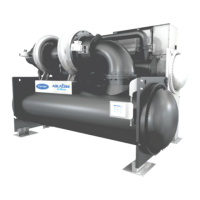
Figure 1 — 19DK Machine Components
Figure 2 — Control Center
Figure 3 — Control Wiring Schematic
Figure 4 — Control Sequence
Figure 5 — 19DK Leak Test Sequence and Procedures
Figure 6 — Purge Valve and Switch Settings
Figure 7 — Purge Component Location
Figure 8 — Flow Chamber Poppet Valve Detail
Figure 9 — Guide Vane Linkage (Closed Position)
Figure 10 — Refrigeration and Motor Cooling Cycles
Figure 11 — Lubrication Cycle
Figure 12 — Purge Cycle
Figure 13 — Compressor Fits and Clearances
 Loading...


