16
d. Run the pumpout compressor until the storage tank
pressure reaches 5 psig (34 kPa), 18 in. Hg vacuum
(41 kPa absolute) in Manual or Automatic mode.
e. Turn off the pumpout compressor.
f. Close valves 1a, 1b, 2, 5, and 6.Turn off pumpout
condenser water.
4. Drain the contaminants from the bottom of the storage
tank into a container. Dispose of contaminants safely.
VALVE 1A1B2345671011
CONDITION CCCCCCCCC
6
10
7
8
2
PUMPOUT
RELIEF
VALVE
PUMPOUT
CONDENSER
CHECK
VALVE
CONDENSER
COOLER
STORAGE VESSEL
OIL
SEPARATOR
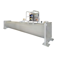
Fig. 10 — Typical Optional Pumpout System Piping Schematic with Storage Tank
NOTES:
1. Maintain at least 2 feet (610 mm) clearance around storage tank for service and operation work.
2. Valve 8 is only applicable for products with linear float valves.
 Loading...