4
Step 3 —
Rig the Storage Tank — The complete
19XR system can be rigged as a single assembly. See the rig-
ging instructions on the label attached to the assembly. Also
refer to the rigging guide (Fig. 4), physical data in Tables 2 and
3, and contact surface and dimensions for the complete sys-
tem in Fig. 5. Lift the assembly only from the 4 points indicated
in the rigging guide. Each rigging cable must be capable of
supporting the entire weight of the assembly.
WARNING
Lifting the assembly from points other than those speci-
fied may result in serious damage to the assembly and
personal injury. Rigging equipment and procedures must
be adequate for assembly. See Tables 2 and 3 for weights.
(These weights are broken down into pumpout unit and
storage tank weights. For the complete assembly weight,
add all components together.)
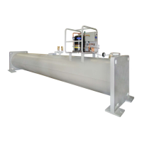
Fig.1 — 19XR Positive Pressure Storage System
CONTACTOR
TERMINAL
STRIP
FUSES
TRANSFORMER
SWITCH
19XR PUMPOUT UNIT
19XR CONTROL BOX (INTERIOR)
a19-2444
FRAME
ASSEMBLY
CONTROL
PANEL
VALVE 2
VALVE 4
VALVE 5
VALVE 3
ENTERING
WATER
LEAVING
WATER CONDENSER
OIL
SEPARATOR
OIL
HEATER
COMPRESSOR
COMPRESSOR
CONTROL
BOX
VALVE
ASSEMBLY
CONDENSER
OIL
SEPARATOR
Fig. 2 — 19XR Pumpout Unit: Typical Chiller Mount
a19-1570ef
 Loading...