6
13
14
15
16
17
18
5
24
23
22
21 20 19
11
9
7
25
26
5
10
27
12
1
2
3
7
6
5
4
11
10
9
8
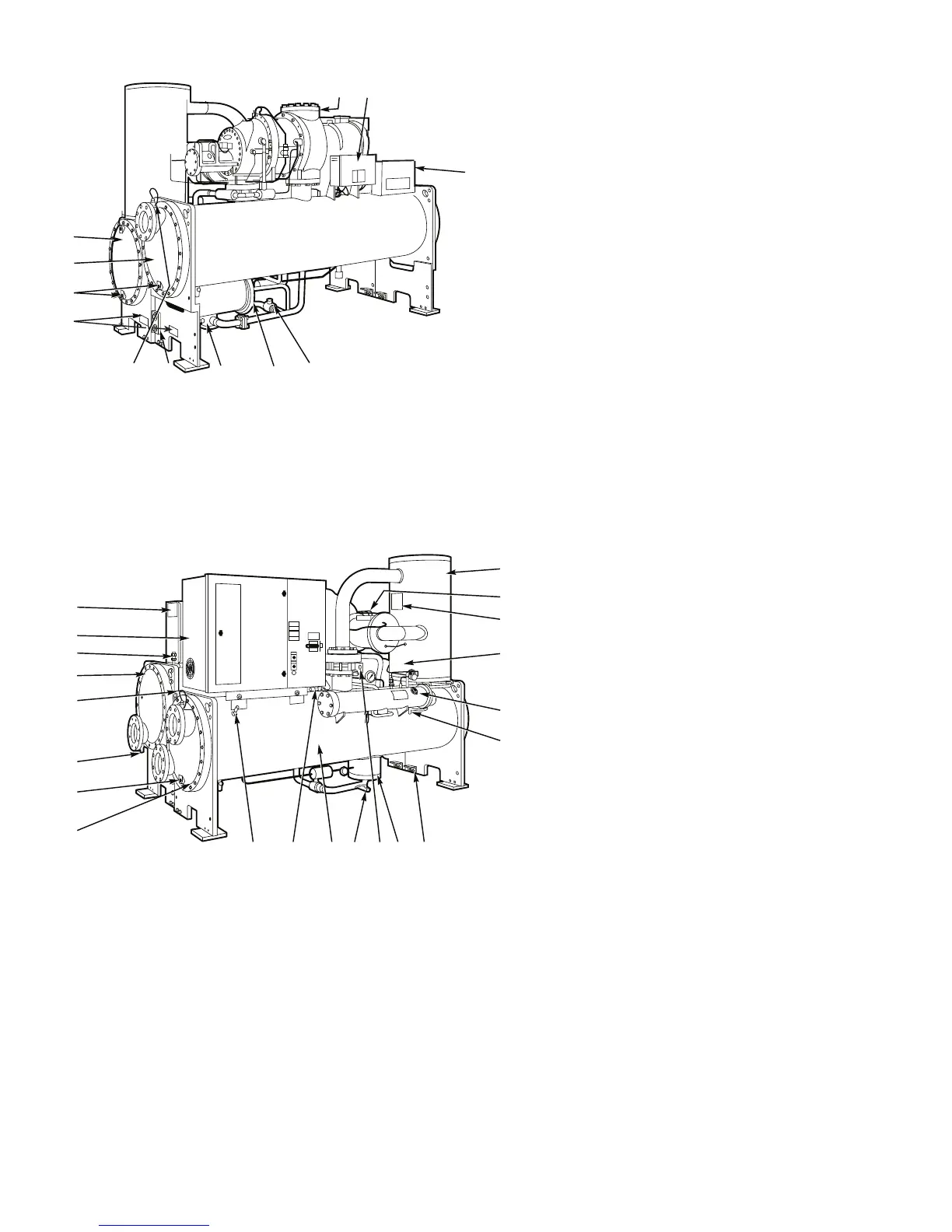
Fig. 2A — Typical 23XL Installation (TC Frame 1 and 2 Chillers)
1
—
Power Panel
2
—
Chiller Visual Controller (CVC)
3
—
Cooler Refrigerant Isolation Valve
4
—
ASME Nameplate, Economizer (Hidden)
5
—
Service Valve
6
—
Take-Apart Rabbet Fit Connector (Lower)
7
—
Cooler Temperature Sensor
8
—
ASME Nameplate, Condenser/Cooler
9
—
Typical Waterbox Drain Port
10
—
Cooler Supply/Return End Waterbox Cover
11
—
Condenser Supply/Return End Waterbox Cover
12
—
Compressor Nameplate (Hidden)
REAR VIEW
13
—
Oil Separator
14
—
ASME Nameplate, Muffler (Hidden)
15
—
ASME Nameplate, Oil Separator
16
—
Cooler Relief Valves (Hidden)
17
—
Oil Sump Filter Assembly
18
—
Oil Charging Valve
19
—
Vessel Separation Feet
20
—
Float Chamber
21
—
Condenser Isolation Valve
(Option or Accessory)
22
—
Refrigerant Charging Valve
23
—
Condenser
24
—
Condenser Relief Valves (Hidden)
25
—
Take-Apart Rabbet Fit Connector
(Upper)
26
—
Unit Mounted Starter (Option)
27
—
Machine Identification Nameplate
FRONT VIEW

 Loading...


