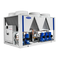
Do you have a question about the Carrier 30RQ-230R and is the answer not in the manual?
Instructions for checking the unit and its accessories upon receipt to ensure no damage or missing parts.
Guidelines for safely moving and lifting the unit, emphasizing the use of designated lifting points.
Recommendations for selecting a suitable installation location, ensuring stability, access, and safety.
Specifies electrical data like voltage, current, power input, and start-up current for 30RB units.
Presents electrical data including voltage, current, power input, and start-up current for 30RBP units.
Details electrical specifications such as voltage, current, power input, and start-up current for 30RQ units.
Details requirements for the unit's power supply, including voltage range and phase imbalance limits.
Provides guidance on selecting appropriate cable sizes based on installation conditions and voltage drop.
Defines the operational limits for water and ambient temperatures for various unit configurations.
Key points and precautions for connecting the hydraulic circuits, including water treatment and protection.
Provides critical warnings and recommendations to prevent frost damage to unit components.
Describes how to control flow rate based on pressure differential for variable-speed pump units.
Explains flow rate control using temperature differential for variable-speed pump units.
Checklist of essential pre-start-up operations, including safety, connections, and refrigerant checks.
Guidelines for commissioning the unit, emphasizing supervision by qualified technicians and system readiness.
Key checks for compressors, hydraulics, and refrigerant charge before initial operation.
Specifies the refrigerant type (R32) and identifies potentially flammable zones around the unit.
Explains the total heat recovery option for hot water production and its physical characteristics.
Describes free cooling options, their operating principles, physical characteristics, and corrosion protection.
Outlines basic maintenance tasks that can be performed by the user, such as visual inspections and cleaning.
Checklist for verifying shipping damage and its potential impact on unit start-up.
Checklist for crucial start-up procedures, including leak checks, voltage imbalance, and heater operation.
Steps to verify water loop volume, inhibitor presence, frost protection, and screen filter.
Procedure to measure and plot pressure drop to determine flow rate for system adjustment.


 Loading...