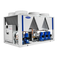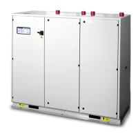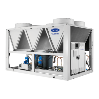
Do you have a question about the Carrier Aquasnap 30RQ and is the answer not in the manual?
| Refrigerant | R-410A |
|---|---|
| Compressor Type | Scroll |
| Type | Air-Cooled Chiller |
| Sound Pressure Level | 72 - 78 dBA |
| Power Supply | 380-415V/3Ph/50Hz |
| Sound Level | 72 - 78 dBA |
| Dimensions | Varies by model (Consult product brochure) |
Instructions for verifying unit and accessory condition, checking for missing parts, and comparing nameplate data.
Safe procedures for moving the unit using lifting equipment, emphasizing designated points and precautions.
Guidelines for correctly positioning the unit, ensuring stability, levelness, access, and protection from environmental factors.
Provides detailed dimensions and lengths for units without the buffer tank module, essential for installation planning.
Specifies required clearances around the unit for safe maintenance access and optimal airflow, crucial for operation.
Presents physical specifications for 30RB 170R-380R models, including sound levels, dimensions, and weight.
Details electrical data for 30RB 170R-950R units, covering power supply, current draw, and start-up current.
Specifies the short-circuit withstand current ratings for the units, including associated protection.
Defines the requirements for the unit's power supply, voltage range, and references for connection details.
Provides crucial safety precautions for connecting control wiring and lists essential devices for field installation.
Specifies the operational limits for units, detailing temperature ranges for various conditions and unit configurations.
Lists minimum and maximum water flow rates for heat exchangers, crucial for system design and performance.
Essential guidelines for hydraulic circuit connection, water treatment, and system integrity checks.
Illustrates hydraulic circuit diagrams and lists key components for units, aiding in proper connection.
Explains flow rate control via pressure differential for variable-speed pump units, detailing setpoint adjustments.
Presents graphs illustrating available static system pressure versus water flow rate for different pump configurations.
A comprehensive checklist for pre-start-up verification, ensuring all safety and installation requirements are met.
Details the essential steps and precautions for unit commissioning, emphasizing safety and proper setup.
Describes fan motor specifications, including efficiency, speed, insulation, and regulatory compliance.
Explains the role of VFDs in optimizing fan speed for energy efficiency and performance based on operating conditions.
Details the features and usability of the SmartVuTM control interface, including its screen, menus, and security.
Provides a detailed overview of available unit options, their descriptions, advantages, and applicability.
Explains the partial heat recovery option for producing hot water using desuperheating compressor discharge gases.
Describes the total heat recovery option for reducing energy consumption by producing hot water.
Outlines advanced maintenance tasks requiring specific expertise in electrical, hydraulic, and mechanical systems.
Provides a table of tightening torques for various electrical connections to ensure secure and safe operation.
Guidance on safe disassembly, handling of hazardous substances, and component sorting for recycling or disposal.
Instructions for the proper end-of-life management of the unit, emphasizing professional disassembly and disposal.
Checklist for verifying the unit's condition, including shipping damage, levelness, and proper electrical connections.
Checklist to ensure the proper operation of air handling units, valves, and pumps before unit start-up.


 Loading...