Do you have a question about the Carrier AquaSnap 30RB 522 and is the answer not in the manual?
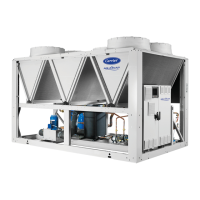
| Model | 30RB 522 |
|---|---|
| Type | Air-Cooled Chiller |
| Cooling Capacity | 522 kW |
| Refrigerant | R-410A |
| Compressor Type | Scroll |
| Power Supply | 400V/3Ph/50Hz |
| Sound Level | 75 dB(A) |
Essential safety checks before unit installation and startup to prevent damage or injury.
Safety precautions for personnel performing maintenance on electrical and refrigerant systems.
Critical safety measures for repairing faults, handling refrigerants, and working with pressurized systems.
Guidelines for selecting an appropriate installation location considering access, environment, and structural support.
Comprehensive pre-startup checks of the installation, refrigeration system, and electrical connections.
Electrical data for standard and option 280 units, including current draw, power input, and voltage.
Information on short-circuit stability current and fuse assignments for TN and IT systems.
Requirements for the power supply voltage, range, and connection details.
Guidelines for checking and acceptable limits for voltage phase imbalance.
Information on standard and optional disconnect switches for power connection.
Crucial precautions for water circuit connections, fluid compatibility, and system protection.
Diagrams and components for units equipped with hydronic modules.
Hydronic connection diagrams for specific module options.
Measures and options for protecting the hydronic circuit and unit components from freezing.
Step-by-step guide for adjusting water flow rate using control valves and interpreting pressure drops.
Description of hermetic scroll compressors, their features, and safety devices.
Information on high-pressure safety switches with automatic reset located on each circuit.
More advanced maintenance tasks requiring specific skills, including electrical and mechanical checks.
Maintenance operations requiring manufacturer expertise, such as component replacement.
Checklists for shipping damage, equipment level, and air handling system status.
Checklist items for unit start-up, voltage imbalance, water loop, and pressure drop verification.
Instructions for QUICK TEST, final start-up, and recording stabilized temperatures and pressures.


