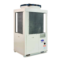
Do you have a question about the Carrier Aquasnap 30RB 050R and is the answer not in the manual?
Guidance on safely moving and lifting the unit using appropriate equipment.
Instructions for outdoor installation, site requirements, and ensuring adequate space.
Table detailing physical properties like sound levels, dimensions, and weights for the units.
Notes and values for electrical data including voltage, current, and power.
Data on short-circuit current withstand capability for TN systems.
Electrical data for pumps and motors in the hydraulic module.
Notes on compressor electrical data, including current and power factors.
Requirements for the unit's power supply, including voltage and phase imbalance.
Guidelines for selecting appropriate cable sizes for power connections.
Defines the operating limits for air and water temperatures for the units.
Curves illustrating pressure drop versus water flow rate for heat exchangers.
Precautions and recommendations for connecting hydraulic circuits and heat exchangers.
Details on hydraulic module compatibility and schematic diagrams for water circuits.
Information, cleaning, and flow rate adjustment for fixed-speed pump hydraulic modules.
Control based on maintaining a constant pressure differential.
Control based on maintaining a specific temperature difference.
Charts showing available static pressure for high pressure pumps.
Comprehensive checklist of installation and safety checks before unit start-up.
Steps for commissioning the unit, including safety device verification.
Key checks for compressors, hydraulics, and refrigerant charge.
Details on hermetically sealed scroll compressors and their features.
Details on fan motor assemblies, impeller material, and insulation.
Overview of the SmartVuT™ control interface and its features.
Controls drycooler for energy savings at low outdoor temperatures.
Details on hydraulic module components like pump, filter, and relief valve for fixed-speed operation.
Details on hydraulic module with variable speed pump controlled by VFD.
Instructions for connecting and configuring two units for master/slave operation.
Information on units with fans providing available pressure, including discharge connections.
Data for calculating fan performance based on pressure drop and speed.
Details on the brine option, including glycol concentration and frost protection.
Basic maintenance tasks for users, including visual inspections and cleaning.
Advanced maintenance requiring expertise in electrical, hydraulic, and mechanical systems.
Specialized maintenance performed only by manufacturer-approved personnel.
Table of torque values for tightening electrical connections.
Table of torque values for tightening main structural fastenings.
Recommendations for inspecting and cleaning air heat exchanger coils.


 Loading...