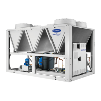
Do you have a question about the Carrier Aquasnap 30RB 040R and is the answer not in the manual?
| Compressor Type | Scroll |
|---|---|
| Refrigerant | R-410A |
| Power Supply | 400V / 3ph / 50Hz |
| Sound Power Level | 82 dB(A) |
| Cooling Capacity | 40.0 kW |
Table detailing physical characteristics like sound levels, dimensions, weight, and refrigerant details.
Electrical specifications including voltage, power input, current draw, and start-up current for various models.
Data on the unit's ability to withstand short-circuit currents and associated protective devices.
Electrical data for pumps and motors integrated into the hydraulic module, including efficiency and power.
Detailed electrical parameters for individual compressors, including current and power factor.
Chart showing which compressor models are used in each circuit for different unit configurations.
Explanations and notes regarding electrical data, environmental conditions, and compatibility standards.
Requirements for the unit's power supply, including voltage range and phase imbalance limits.
Guidance on calculating and acceptable limits for voltage phase imbalance to prevent unit misuse.
Information on the single connection point and earth connection for the unit's power supply.
Guidelines for selecting appropriate cable sizes for power connections, considering voltage drop and routing.
Defines the operational limits for water and air temperatures for various unit configurations.
Key checks and recommendations before connecting hydraulic circuits to heat exchangers.
Comprehensive checklist of pre-start-up inspections for the unit and connected systems.
Steps and precautions for commissioning the unit, including safety checks and operational tests.
Critical checks for compressors, hydraulics, and refrigerant charge before and during start-up.
Overview of the SmartVuT™ control interface, its features, and user adaptability.
Fields for recording job details, location, contractor, distributor, and start-up personnel.
Fields to record unit model and serial number, and air handling equipment details.
Sections to record model and serial number for each compressor in Circuit A and Circuit B.
Fields for manufacturer, model, and serial number of air handling units and accessories.
Checklist for initial inspection of the unit for shipping damage and start-up readiness.
Checklist for verifying the operational status of air handling units, valves, piping, and pumps.


 Loading...