3
PHYSICAL DATA
UNIT SIZE SERIES 24---30 36---30 48---30 60---30
Operating Weight (lb) 330 330 330 350
Shipping Weight (lb) 367 367 367 387
Compressor Type 2 --- S t a g e S c r o l l
REFRIGERANT Puron® (R--- 410A)
Control TXV (Puron® Hard Shutoff)
Charge (lb) 14.0 12.75 11.75 11.75
COND FAN Forward Swept Propeller Ty pe, Direct Drive
Air Discharge Vertical
Air Qty (CFM) 2850/3250 2900/3450 3300/3800 3800/4250
Motor HP 1/5
Motor RPM 625/735 582/690 660/765 742/828
COND COIL
Face Area (Sq ft) 24.40
Fins per In. 20
Rows 2
Circuits 8
VALVECONNECT.(In.ID)
Vapor 7/8
Liquid 3/8
REFRIGERANT TUBES* (In. OD)
Vapor (0---80 Ft Tube Length) 7/8 7/8 7/8 1 --- 1 / 8
Liquid (0---80 Ft Tube Length) 3/8
* For tubing sets between 80 and 200 ft. horizontal or 20 ft. vertical differential (250 ft. Total Equivalent Length), consult the
Long Line Guideline.
Note: See unit Installation Instruction for proper installation.
VAPOR LINE SIZING AND COOLING CAPACITY LOSS
PURON REFRIGERANT 2--STAGE AIR CONDITIONER APPLICATIONS
Unit Nomi-
nal Size
(Btuh)
Acceptable
Liquid Line
Diameters
(in. O. D.)
Accept-
able Va-
por Line
Diameters
(In. O.D. )
Standard Application Long Line Application Requires Accessories
25 50 80 80+ 100 125 150 175 200 225 250
24000
2 --- S t a g e
Puron AC
3/8
5/8 0 1 1 1 2 3 3 4 4 5 6
3/4 0 0 0 0 0 1 1 1 1 1 2
7/8 0 0 0 --- --- --- --- --- --- --- ---
36000
2 --- S t a g e
Puron AC
5/8 1 2 4 4 5 6 7 9 10 11 13
3/4 0 0 1 1 1 2 2 3 3 4 4
7/8 0 0 0 0 0 1 1 1 1 2 2
48000
2 --- S t a g e
Puron AC
3/4 0 1 2 2 3 4 5 5 6 7 8
7/8 0 0 1 1 1 2 2 2 3 3 4
60000
2 --- S t a g e
Puron AC
3/4 1 2 4 4 5 6 7 9 10 11 12
7/8 0 1 2 2 2 3 4 4 5 5 6
1 --- 1 / 8 0 0 0 0 1 1 1 1 1 1 2
Standard Length = 80 ft. or less total equivalent length
NOTE: Dashes (--) represent insufficient oil return to the compressor in heating mode. Use smaller tube diamter in this area.
Applications in this area are long line. Accessories are required as shown recommended on Long Line Application Guidelines
Applications in this area may have height restrictions that limit allowable total equivalent length, when outdoor unit is below indoor unit
See Long Line Application Guidelines
LONG LINE APPLICATION: An application is considered
”Long line” when the total equivalent tubing length exceeds 80
ft. or when there is more than 20 ft. vertical separation between
indoor and outdoor units. These applications require additional
accessories and system modifications for reliable system
operation.
The maximum allowable total equivalent length is 250 ft. The
maximum vertical separation is 200 ft. when outdoor unit is
above indoor unit, and 80 ft. when the outdoor unit is below the
indoor unit. Refer to Accessory Usage Guideline below for
required accessories. See Long Line Application Guideline for
required piping and system modifications. Also, refer to the table
below for the acceptable vapor tube diameters based on the total
length to minimize the cooling capacity loss.
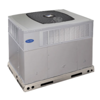
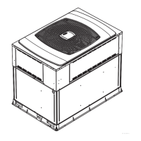
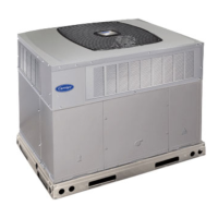
24ANA1
 Loading...