Do you have a question about the Carrier 24SCA4 and is the answer not in the manual?
Important safety precautions for installation personnel and users.
Instructions for connecting refrigerant piping to the unit.
Detailed steps for making sweat connections for refrigerant tubing.
Procedure for evacuating the system to remove air and moisture.
Essential checks like pressure proof and leak detection.
Procedure for charging TXV systems using the subcooling method.
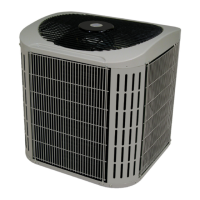
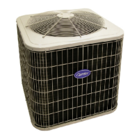
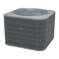
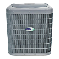
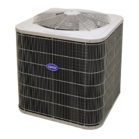
This document outlines the installation, operation, and maintenance procedures for the Carrier Comfort Series™ Air Conditioner with Puron® Refrigerant, available in 1.5 to 5 nominal tons (models 24SCA4 and 24SCA5). It emphasizes safety, proper installation techniques, and routine maintenance to ensure optimal performance and longevity of the unit.
The Carrier Comfort Series™ Air Conditioner is designed to provide cooling for residential and light commercial applications. It utilizes Puron® refrigerant, an environmentally friendly alternative to older refrigerants. The unit works in conjunction with an indoor coil and fan coil or furnace to circulate refrigerant, absorb heat from the indoor air, and release it outdoors, thereby lowering the indoor temperature. The system is engineered for efficiency and reliable operation, contributing to a comfortable indoor environment.
The installation process is detailed, beginning with safety considerations. It stresses that only EPA-qualified personnel with appropriate certification should install the appliance. Improper installation can lead to serious hazards, including explosion, fire, electrical shock, personal injury, or property damage. Installers are advised to follow all safety codes, wear protective gear (safety glasses, clothing, gloves), and have a fire extinguisher available, especially during brazing operations.
The unit should be located away from windows, patios, and decks to minimize operational sound disturbance. Proper sizing of vapor and liquid tubes is crucial for unit capacity, and refrigerant tubes should be run with minimal bends. Slack should be left between the structure and the unit to absorb vibration, and wall openings for tubes must be sealed with RTV or silicon-based caulk. Direct contact between tubing and water pipes, ductwork, floor joists, wall studs, floors, and walls should be avoided. Tubing should not be rigidly suspended, and proper insulation of the vapor tube is essential. Hanger straps, if used, should conform to the insulation shape and be isolated from it with metal sleeves. Provisions for expansion and contraction of long piping runs are also necessary. Piping and fittings must be protected from environmental effects like dirt and debris and installed to minimize hydraulic shock. Certified piping and components are required to prevent corrosion, and flexible pipe elements must be protected from mechanical damage and excessive stress.
The unit is designed for installation at elevations up to 10,000 feet (3000 meters) above sea level. It must be installed on a solid, level mounting pad or platform. For rooftop applications, the unit should be placed above a load-bearing wall and isolated from the structure to minimize vibration transmission. Local codes for rooftop installations, including potential wind baffles, must be consulted. The unit must be level within ±2° (±3/8 in./ft.±9.5 mm/m).
Clearance requirements are specified for airflow, wiring, refrigerant piping, and service access. A minimum of 24 inches (610 mm) clearance is needed at the service end, and 48 inches (1219 mm) above the unit. For proper airflow, 6 inches (152 mm) clearance is required on one side and 12 inches (305 mm) on all remaining sides. A distance of 24 inches (610 mm) between units, or 18 inches (457 mm) if no overhang within 12 feet (3.67 m), is necessary. The unit should be positioned to prevent water, snow, or ice from falling directly onto it. For units with louver panels, 24 inches (610 mm) clearance between units is mandatory. Rooftop units must be at least 6 inches (152 mm) above the roof surface. The minimum outdoor operating ambient in cooling mode without accessories is 55°F (13°C).
Before any system repair or final disposal, pressure must be relieved, and all refrigerant recovered, as federal regulations prohibit venting refrigerant into the atmosphere. The document provides a table of recommended liquid and vapor tube diameters based on unit size. It emphasizes that if any refrigerant tubing is buried, a 6-inch (152 mm) vertical rise at the service valve is required, and tubing should not be buried more than 36 inches (914 mm). For longer tubing runs or specific conditions, the Residential Piping and Long Line Guideline should be consulted.
The outdoor unit can be connected to the indoor section using accessory tubing packages or field-supplied refrigerant-grade tubing. The factory-supplied liquid-line filter drier must always be installed. When brazing, service valves must be wrapped in a heat-sinking material, such as a wet cloth, to prevent damage. Refrigerant-grade tubing should be used, and tube ends cleaned before insertion into service valve stubs. Brazing should be done with Sil-Fos or Phos-copper alloy. After brazing, the system must be leak-tested.
The refrigerant tubing and indoor coil must be evacuated to 500 microns using the deep vacuum method to eliminate contamination and moisture. The alternate triple evacuation method can also be used. The system should hold a vacuum of 1000 microns for approximately 7 minutes to indicate a tight, dry system. A pressure proof check with a nitrogen charge of about 200 psi is required, and the pressure must not decrease for 1 hour. Leak checking should be performed without flames or ignition sources.
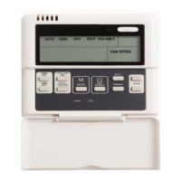
Field wiring must comply with local and national fire, safety, and electrical codes, and the voltage must be within the limits specified on the unit rating plate. The main electrical disconnect switch must be in the OFF position before installation, modification, or servicing. There may be more than one disconnect switch, and all must be locked out and tagged. Copper wire must be used between the disconnect switch and the unit. A branch circuit disconnect of adequate size, per NEC Section 440-14, must be installed within sight and readily accessible from the unit. The unit cabinet must have an uninterrupted ground connection to minimize personal injury in case of an electrical fault. Control wiring (24-v) should be routed through the grommet and connected according to the thermostat installation instructions. No. 18 AWG color-coded, insulated wire is recommended, but No. 16 AWG wire should be used for thermostat distances over 100 feet (30 m) to avoid excessive voltage drop. All wiring must be NEC Class 2 and separated from incoming power leads.
Before starting the unit, the liquid and vapor service valves must be fully opened. The unit is shipped with valve stems front-seated (closed) and caps installed; these caps should be replaced finger-tight and tightened an additional 1/12 turn after opening the system to refrigerant flow. Electrical disconnects should be closed to energize the system. The room thermostat should be set to the desired temperature (below indoor ambient) and the fan control to ON or AUTO. The unit should operate for 15 minutes to allow the system to stabilize before checking the refrigerant charge.
For units with a cooling mode TXV (Thermostatic Expansion Valve), charging is done by the subcooling method. The unit should operate for at least 15 minutes before checking the charge. Liquid service valve pressure and liquid line temperature near the outdoor coil are measured. The required subcooling temperature is found on the unit rating plate. Refrigerant is added if the liquid line temperature is higher than indicated or reclaimed if it is lower, with a tolerance of ±3°F (±1.7°C).
For units with indoor pistons, charging is done by the superheat method. This procedure is valid when indoor airflow is within ±21 percent of its rated CFM. Measurements include suction pressure, suction temperature, outdoor air dry-bulb temperature, and indoor air wet-bulb temperature. The superheat is determined from a provided table, and refrigerant is added or reclaimed to reach the charted suction line temperature. Refrigerant should be added in liquid form into the suction service port using a flow-restricting device. Optimum performance is achieved with a 10°F suction superheat at the suction service valve under specific ambient conditions.
3-phase units include a small circuit board to monitor line voltage. A flashing LED indicates a phase problem (reversed phase), requiring the interchange of two field-wiring leads on the unit contactor after disconnecting power. A solid ON LED indicates normal operation.
For continuing high performance and to minimize possible equipment failure, periodic maintenance must be performed on the equipment. The frequency of maintenance may vary depending on geographic areas, such as coastal applications. The owner's manual provides detailed information on maintenance requirements.
Before leaving the job site, installers must ensure that all wiring is routed away from tubing and sheet metal edges to prevent rub-through or pinching. All wiring and tubing must be secure, and all panels and covers securely fastened. Service valve stem caps must be tightened to 1/12-turn past finger-tight. The owner's manual should be left with the owner, and the system operation and periodic maintenance requirements explained. A dealer installation checklist should be filled out and placed in the customer file.
When breaking into the refrigerant circuit for repairs, the refrigerant must be safely removed using a recovery pump certified for flammable refrigerants. The circuit should then be purged with nitrogen gas and evacuated to 1500 microns. The vacuum should be broken with a nitrogen purge, ensuring the vacuum pump outlet is not near a potential ignition source. The circuit can then be opened by cutting or brazing.
If equipped with a crankcase heater, power must be supplied to it for a minimum of 24 hours before starting the unit. This is required if refrigerant tubing is longer than 80 feet (24 m) or if the outdoor unit is 35 feet (6 m) below the indoor unit.
The document includes a table of accessory usage, indicating which accessories are required for low-ambient cooling applications (below 55°F/12.8°C), long line applications, and sea coast applications (within 2 miles/3.22 km). These accessories include ball bearing fan motors, compressor start assist capacitors and relays, crankcase heaters, evaporator freeze thermostats, hard shut-off TXVs, liquid line solenoid valves, MotorMaster® controls or low-ambient pressure switches, support feet, and winter start controls. The use of non-manufacturer approved parts and accessories can invalidate the warranty and lead to fire risk, equipment malfunction, and failure.
Carrier provides training resources through its My Learning Center, accessible via HVACpartners credentials at www.mlctraining.com, to help strengthen careers and businesses in the HVAC industry.
| Type | Split System Air Conditioner |
|---|---|
| Refrigerant | R-410A |
| HSPF Rating | Not Applicable |
| Voltage | 208/230V |
| Phase | 1 |
| Compressor Type | Single-Stage |
| SEER Rating | Up to 14 |