EasyManua.ls Logo

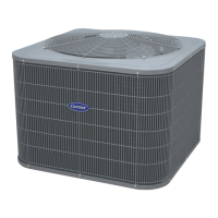
Carrier 25HCA User Manual

Carrier 25HCA
14 pages
To Next Page IconTo Next Page
Page #1 background imageLoading...
Page #1 background image
Installation Instructions
25HCA
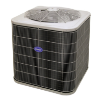
Comfortt Series Heat Pump with Puronr Refr iger a n t
Sizes 18 To 60
11/2To5NominalTons
A05341
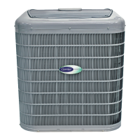
Fig. 1 --- 25HCA
NOTE: Read the entire instruction manual before starting the
installation.
TABLE OF CONTENTS
PAGE
SAFETY CONSIDERATIONS 2.......................
INSTALLATION RECOMMENDATIONS 2.............
INSTALLATION 3--12..............................
Step 1 -- Check Equipment & Jobsite 3...............
Step 2 -- Install on Solid Pad 3......................
Step 3 -- Clearance Requirements 3..................
Step 4 -- Operating Ambient 3......................
Step 5 -- Elevate Unit 3...........................
Step 6 -- Install TXV 3 -- 4.........................
Step 7 -- Check Defrost Thermostat 5.................
Step 8 -- Make Piping Connections 5 -- 7..............
Step 9 -- Make Electrical Connections 7 -- 8............
Step 10 -- Compressor Crankcase Heater 8.............
Step 11 -- Install Electrical Accessories 8..............
Step 12 -- Start-- Up 9 -- 11..........................
Step 13 -- Check Charge 12.........................
Step 14 -- Final Checks 12..........................
CARE AND MAINTENANCE 12......................
PURON REFRIGERANT QUICK REFERENCE GUIDE 14
Question and Answer IconNeed help?

Do you have a question about the Carrier 25HCA and is the answer not in the manual?

Carrier 25HCA Specifications

General IconGeneral
Model Number25HCA
CategoryHeat Pump
Refrigerant TypeR-410A
Operating Voltage (VAC)208/230
Phase1
HSPF Rating9
Sound Level (dBA)72
Dimensions (H x W x D, in)31.5 x 34.5 x 31.5

Summary

Safety Considerations

Installation Recommendations

Installation

Step 1 Check Equipment & Jobsite

Verify unit condition and installation site suitability before proceeding.

Step 2 Install on a Solid, Level Mounting Pad

Securely mount the unit on a stable, level pad, using tie-down bolts if required.

Step 3 Clearance Requirements

Ensure adequate space around the unit for airflow, wiring, piping, and service access.

Step 4 Operating Ambient

Note the minimum and maximum outdoor operating ambient temperatures for cooling and heating.

Step 5 Elevate Unit

Raise the unit to provide clearance above estimated snowfall levels and ensure proper drainage.

Step 6 Install TXV

Replace existing piston or R-22 TXV with a factory-approved Puron TXV.

Step 7 Check Defrost Thermostat

Confirm the defrost thermostat is properly located and securely attached to the stub tube.

Step 8 Make Piping Connections

Connect liquid and vapor refrigerant lines using proper brazing and leak testing techniques.

Step 9 Make Electrical Connections

Connect power and control wiring according to codes, ensuring proper grounding and voltage.

Step 10 Compressor Crankcase Heater

Power the crankcase heater at least 24 hours before starting unit to prevent oil dilution.

Step 11 Install Electrical Accessories

Follow individual instructions for installing any additional electrical accessories.

Step 12 Start-Up

Follow procedures to safely start the system, check refrigerant charge, and set thermostat.

Step 13 Check Charge

Verify system refrigerant charge using subcooling or weight methods per unit rating plate.

Step 14 Final Checks

Ensure all wiring, tubing, and panels are secure before leaving the job site.

Care and Maintenance

Puron Refrigerant Quick Reference Guide

Related product manuals