5
SPECIFICATIONS (CONT)
Table 4—Heat Pump
HEAT PUMP
System
Size 24 30 34 34 34
Outdoor Model
25HHA424A003
224ANS030000
25HHA430A003
224ANS036000
25HHA436A003
224APS036000
25HHA436A005
224AES036000
25HHA436A006
224ANS048000
Indoor Model 40MKQB34C--3 40MKQB34C--3 40MKQB34C--3 40MKQB34C--3 40MKQB34C--3
Energy Star NO NO NO NO NO
Performance
Cooling Rated Capacity Btu/h 23,400 28,400 32,600 32,600 32,600
SEER 14 14 14 14 14
EER 11.2 12.2 12.2 12.2 12.2
Heating Rated Capacity Btu/h 20,200 29,000 33,000 33,000 33,000
HSPF 8.2 8.2 8.2 8.2 8.2
COP W/W 4.24 4.1 3.94 3.94 3.94
Controls
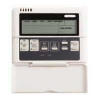
Wireless Remote Controller (°F/°C
Convertible)
Standard Standard Standard Standard Standard
Wired Remote Controll er (°F/°C Convertible) Optional Optional Optional Optional Optional
Operating
Range
Cooling Outdoor DB Min - Max °F
55~125 (-20°F w /
Low-Ambient Kit)
55~125 (-20°F w /
Low-Ambient K it)
55~125 (-20°F w /
Low-Ambient K it)
55~125 (-20°F w /
Low-Ambient Kit)
55~125 (-20°F w /
Low-Ambient K it)
Heating Outdoor DB Min - Max °F 17~75 17~75 17~75 17~75 17~75
Cooling Indoor DB Min -Max °F 64~90 64~90 64~90 64~90 64~90
Heating Indoor DB Min -Max °F 32~80 32~80 32~80 32~80 32~80
Piping
Total Piping Length** Ft. 200' 200' 200' 200' 200'
Drop (OD above ID) Ft. 200' 200' 200' 200' 200'
Lift (OD below ID) Ft. 65' 65' 65' 65' 65'
Outdoor Pipe Connection Size - Li quid In. 3/8" 3/8" 3/8" 3/8" 3/8"
Outdoor Pipe Connection Size -
Suction
In. 3/4" 3/4" 7/8" 7/8" 7/8"
Indoor Pi pe Connection Size - Liquid* In. 3/8" 3/8" 3/8" 3/8" 3/8"
Indoor Pi pe Connection Size - Suction In. 3/4" 3/4" 3/4" 3/4" 3/4"
Refrigerant
Type R-410A R-410A R-410A R-410A R-410A
Design Pressure PSIG 550 550 550 550 550
Metering Device Type B Accurator
Charge Lb. 7.7 12.1 12.3 12.3 12.3
Outdoor
Coil
Face Area Sq. Ft. 7.3 12.1 12.1 12.1 12.1
No. Rows 2 2 2 2 2
Fins per inch 20 20 20 20 20
Circuits 3 6 5 5 5
Indoor
Coil
Face Area (sq. ft.) Sq. Ft. 5.6 5.6 5.6 5.6 5.6
No. Rows 3 3 3 3 3
Fins per inch 18 18 18 18 18
Circuits 12 12 12 12 12
Compressor
Type Scroll Scroll Scroll Scroll Scroll
Model ZP21K5E-PFV-130 ZP24K5E-PFV-130 ZP29K5E-PFV-130 ZP29K5E-TF5-130 ZP29K5E-TFD-130
Electrical
Outdoor Voltage, Phase, Cycle
V/Ph/
Hz
208/230-1-60 208/230-1-60 208/230-1-60 208/230-3-60 460-3-60
Indoor Vol tage, Phase, Cycle
V/Ph/
Hz
208/230-1-60 208/230-1-60 208/230-1-60 208/230-1-60 208/230-1-60
Power Supply Indoor and outdoor uni ts have dedi cated power suppl y
MCA (Outdoor) A. 16.5 17.2 19 12.8 7.6
MOCP - Fuse Rating (Outdoor) A. 25 30 30 20 15
MCA (Indoor) A. 1 1 1 1 1
MOCP - Fuse Rating (Indoor) A. 15 15 15 15 15
Outdoor
Unit Width In. 36.9 44.5 44.5 44.5 44.5
Unit Height In. 31.1 37.1 37.1 37.1 37.1
Unit Depth In. 14.6 17.1 17.1 17.1 17.1
Net W eight Lbs. 161 196 197 197 197
Airflow CFM 1,285 2,615 2,615 2,615 2,615
Indoor
Unit Width Body In. 33.1 33.1 33.1 33.1 33.1
Unit Height Body In. 33.1 33.1 33.1 33.1 33.1
Unit Depth Body In. 11.3 11.3 11.3 11.3 11.3
Net W eight Body Lbs. 68.6 68.6 68.6 68.6 68.6
Unit Width Grille In. 37.4 37.4 37.4 37.4 37.4
Unit Height Grille In. 37.4 37.4 37.4 37.4 37.4
Unit Depth Grille In. 2.2 2.2 2.2 2.2 2.2
Net Weight Grille Lbs. 11.0 11.0 11.0 11.0 11.0
Number of Fan Speeds 3 3 3 3 3
Airflow (lowest to highest) CFM 750/820/1130 750/820/1130 750/820/1130 750/820/1130 750/820/1130
Sound Pressure (lowest to hi ghest) dB(A) 44/48/53 44/48/53 44/48/53 44/48/53 44/48/53
Air throw Data Ft. 16 16 16 16 16
* Liquid line needs to be insulated
** Refer to Ductless Split System Long Line Guide for additional information. Long Line accessories required beyond 80 ft (24.4 m).
 Loading...