27SPA6: Installation Instructions
Manufacturer reserves the right to change, at any time, specifications and designs without notice and without obligations.
2
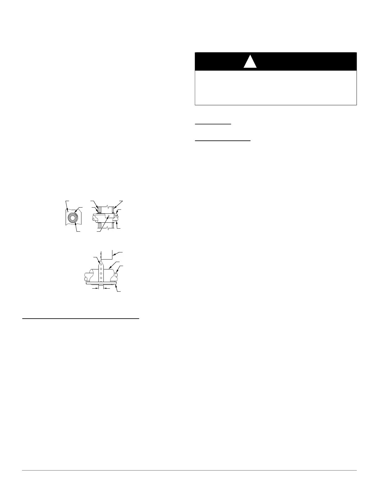
8. Do not suspend refrigerant tubing from joists and studs with a rigid
wire or strap which comes in direct contact with tubing (see Fig. 1).
9. Ensure that tubing insulation is pliable and completely surrounds
vapor tube.
10. When necessary, use hanger straps which are 1 in. (25 mm) wide
and conform to shape of tubing insulation (see Fig. 1).
11. Isolate hanger straps from insulation by using metal sleeves bent to
conform to shape of insulation.
12. Provision shall be made for expansion and contraction of long runs
of piping.
13. Piping and fittings shall be protected as far as possible against
adverse environmental effects. For example, the accumulation of
dirt and debris.
14. Piping should be installed to reduce the likelihood of hydraulic
shock damaging the system.
15. Certified piping and components must be used in order to protect
against corrosion.
16. Flexible pipe elements shall be protected against mechanical
damage, excessive stress by torsion, or other forces. They should be
checked for mechanical damage annually.
17. Piping material, routing, and installation shall include protection
from physical damage in operation and service, and be in
compliance with the national and local codes and standards of the
installation site.
18. When setting up refrigerant piping, precautions shall be taken to
avoid excessive vibration or pulsation.
A07588
Fig. 1 – Connecting Tubing Installation
Refrigerant Tubing Connection Outdoor
IMPORTANT: Maximum liquid–line size is 3/8–in. OD for all
residential applications including long line. Refer to Residential Piping
and Long Line Guideline for further information
IMPORTANT: Always install the factory–supplied liquid–line filter
drier.
If replacing the filter drier, refer to Product Replacement Parts List for
appropriate part number. Obtain replacement filter driers from your
distributor or branch.
INSTALLATION
IMPORTANT: Effective January 1, 2023, all split system and packaged
heat pumps must be installed pursuant to applicable regional efficiency
standards issued by the Department of Energy.
Check Equipment and Job Site
Unpack Unit
Move to final location. Remove carton taking care not to damage unit.
Inspect Equipment
File claim with shipping company prior to installation if shipment is
damaged or incomplete. Locate unit rating plate on unit corner panel. It
contains information needed to properly install unit. Check rating plate
to be sure unit matches job specifications.
Install on a Solid, Level Mounting Pad
If conditions or local codes require the unit be attached to pad, tie down
bolts should be used and fastened through knockouts provided in unit
base pan. Refer to unit mounting pattern in Fig. 2 to determine base pan
size and knockout hole location.
For hurricane tie downs, contact distributor for details and PE
Certification (Professional Engineer), if required.
On rooftop applications, mount on level platform or frame. Place unit
above a load–bearing wall and isolate unit and tubing set from structure.
Arrange supporting members to adequately support unit and minimize
transmission of vibration to building. Consult local codes governing
rooftop applications.
Roof mounted units exposed to winds above 5 mph may require wind
baffles. Consult the Application Guideline and Service Manual –
Residential Split System Air Conditioners and Heat Pumps for wind
baffle construction.
Unit must be level to within ±2° (±3/8 in/ft,±9.5 mm/m) per compressor
manufacturer specifications.
Clearance Requirements
When installing, allow sufficient space for airflow clearance, wiring,
refrigerant piping, and service. Allow 24 in. (610 mm) clearance to
service end of unit and 48 in. (1219 mm) above unit. For proper airflow,
a 6–in. (152 mm) clearance on 1 side of unit and 12–in. (305 mm) on all
remaining sides must be maintained. Maintain a distance of 24 in. (610
mm) between units or 18 in. (457 mm) if no overhang within 12 ft. (4
m). Position so water, snow, or ice from roof or eaves cannot fall
directly on unit.
NOTE: 18” (457 mm) clearance option described above is approved for
outdoor units with wire grille coil guard only. Units with louver panels
require 24” (610 mm) between units.
On rooftop applications, locate unit at least 6 in. (152 mm) above roof
surface.
INSULATION
SUCTION TUBE
LIQUID TUBE
OUTDOOR WALL INDOOR WALL
LIQUID TUBE
SUCTION TUBE
INSULATION
CAULK
HANGER STRAP
(AROUND SUCTION
TUBE ONLY)
JOIST
1” (25.4 mm)
MIN
THROUGH THE WALL
SUSPENSION
CAUTION
!
CUT HAZARD
Failure to follow this caution may result in personal injury.
Sheet metal parts may have sharp edges or burrs. Use care and wear
appropriate protective clothing and gloves when handling parts.