COM
G
G3(Y)
G2(W)
BLACK
WHITE
R
C
R
C
G2
G3
G
RS
H2O
V
Y1
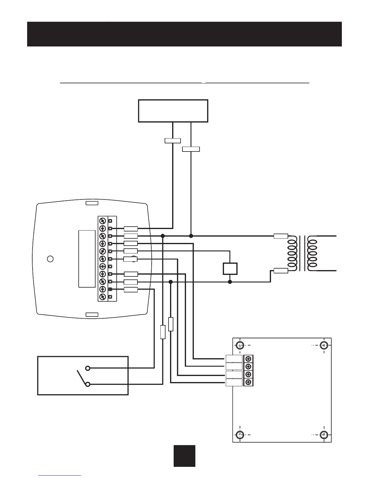
Thermostat
24vac
24 Volt
Water Valve
H
2
0 Changeover Sensor
G100-71520306
Closed Below 60˚
Open Above 75˚
Duct Sensor
G100-71520307
Sample Wiring Diagram
2-Pipe, Low Voltage Valve, H
2
0 Changeover Sensor
Important Note:IfaDuct
sensor is connected to this
thermostat it is suggested
that the fan be programmed
for continuous operation
(step#5,page11ofthe
Owner’sManual)
 Loading...